background image


June 15, 2011 


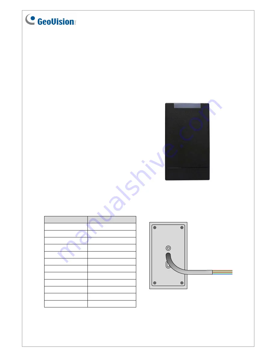
GV- R1352 Card Reader 

The GV-R1352 is a card reader designed to recognize identification cards. Featured with the 

Wiegand and RS-485 outputs, the unit can be connected to any standard access control 

panel. GV-R1352 comes with a weather sealed and IP66 compliant housing for outdoor use.  


1.  Packing List 


1.  GV-R1352 Card Reader x 1 

2.  Screw x 3 

3.  Screw Anchor x 2 

4.  Security Torx 

5.  GV-R1352 Software CD x 1 

6.  GV-R1352 Installation Guide 
 

Front View 


2.  Electric Wire 


Wire Color  

Function 

Red 

DC 12V 

Black 

GND 

Yellow 

Beeper 

Orange 

Green LED 

Light Red 

Red LED 

Green 

Wiegand Data 0 

White 

Wiegand Data 1 

Blue 

RS-485 + 

Light Blue 

RS-485 - 

Gray 

N/A 

Purple 

N/A 

Brown 

N/A 


Rear View


Summary of Contents for GV-R1352

Page 1: ...h a weather sealed and IP66 compliant housing for outdoor use 1 Packing List 1 GV R1352 Card Reader x 1 2 Screw x 3 3 Screw Anchor x 2 4 Security Torx 5 GV R1352 Software CD x 1 6 GV R1352 Installation Guide Front View 2 Electric Wire Wire Color Function Red DC 12V Black GND Yellow Beeper Orange Green LED Light Red Red LED Green Wiegand Data 0 White Wiegand Data 1 Blue RS 485 Light Blue RS 485 Gra...

Page 2: ...Beeper and LED Indicator later in this installation guide 4 Connecting GV R1352 to GV AS Controller GV R1352 is compatible with GV AS100 110 120 400 Controllers but the connection between GV R1352 and the controller varies with different controller models The following diagrams illustrate how to connect GV R1352 to GV AS400 Controller through Wiegand or RS 485 interface 4 1 Connecting through Wieg...

Page 3: ... Wire GV R1352 readers to GV AS Controller Note If only one GV R1352 reader is connected to GV AS Controller through RS 485 interface you can skip steps 1 and 2 and the default ID number for the reader will be 0 4 2 1 Connecting GV R1352 to a Computer to Access GV RK1352 Config AP Using the GV RK1352 Config AP included in the software CD you can define the ID numbers of multiple readers connected ...

Page 4: ...ion USB Devices Driver 3 In the GeoVision USB Driver Installer window that appears select Install 4 Go back to the Install Program window and select Run GV RK1352 Config Utility This dialog box appears 5 Type the barcode number of GV R1352 in the Serial ID box The barcode number is on the rear panel of GV R1352 6 Select the COM port that is connected to GV R1352 and click Open COM The red square n...

Page 5: ...olific USB to Serial Comm Port The COM port showing in the entry indicates the COM number currently in use 7 Select an ID number for the reader The ID number ranges from 0 to 7 8 Click Setup GO The settings are sent to GV R1352 Note If you select the wrong COM port of GV R1352 a Fail Please check Serial ID and comport message will appear when you click the Setup GO button Go to Windows Device Mana...

Page 6: ...less readers to GV AS400 Controller Wire Color Function Black GND Light Blue RS 485 Blue RS 485 Red DC 12V Connecting five or more readers to GV AS400 Controller For readers five to eight connect the RS 485 cable to the RS 485 interface on GV AS400 Controller and then connect the 12V power output and GND of the reader to a 10V to 13V DC power output on the GV AS Power Board Wire Color Function Bla...

Page 7: ...0 Controller can control up to four doors you need to specify which door each reader controls 1 On the GV AS400 Web interface click Extend Reader This dialog box appears 2 Select the ID number of the reader and type its barcode number The ID number should be the same with the one you configure through the GV RK1352 Config AP 3 Select a door gate for the reader from the Function drop down list Clic...

Page 8: ...nterface of GV AS Controller 6 1 Setting up Beeper and LED on GV RK1352 Config AP To enable the external controls of the Beeper and LED start the GV RK1352 Config AP according to the instructions in Accessing the GV RK1352 Config AP earlier in this installation guide After GV RK1352 Config AP is started you have to enable the external controls and set the GV R1352 to be slave 1 Start the GV RK1352...

Page 9: ...k Setup GO The settings are sent to GV R1352 After the above settings you need to connect the Beeper Red LED and Green LED wires from GV R1352 to GV AS Controller 6 2 Wiring the Beeper and LED to GV AS Controller To wire the beeper and LED to GV AS Controller follow these steps We will use GV AS400 Controller as an example Connect the control wires of GV R1352 s Beeper Red LED or Green LED to any ...

Page 10: ...00 Web interface click Output Setting The page below appears 2 From outputs 9 12 select a door and select Beeper Green LED Red LED or Invert Red LED Click Submit Beeper Enables the external control of Beeper Green LED Changes the standby color to blue When a card is read the LED flashes green RED LED Changes the standby color to red When a card is read the LED flashes blue Invert Red LED Changes t...

Page 11: ...is updated WARNING The interruption of power supply during updating causes not only update failures but also damages to the device In this case please contact your sales representative and send your device back to GeoVision for repair To upgrade firmware 1 Insert the Software CD and select Run Firmware Update Utility This dialog box appears 2 Select the COM port of GV R1352 3 Click the Browse butt...

Page 12: ...e LED Beeper Buzzer Reader Color Black Operating Temperature 20 C 60 C 4 F 140 F Operating Humidity 10 90 no condensation Dimensions W x H x D 65 80 x 115 6 x 20 5 mm 4 6 x 2 6 x 0 8 in Weight 120 g 0 26 lb Certification IP66 CE FCC RoHS 9 The number of GV R1352 supported by GV AS Controllers GV R1352 Interface GV AS Controller Model Wiegand RS 485 GV AS100 1 1 GV AS110 120 1 Not support GV AS100 ...

Reviews: