10
Network Diagrams
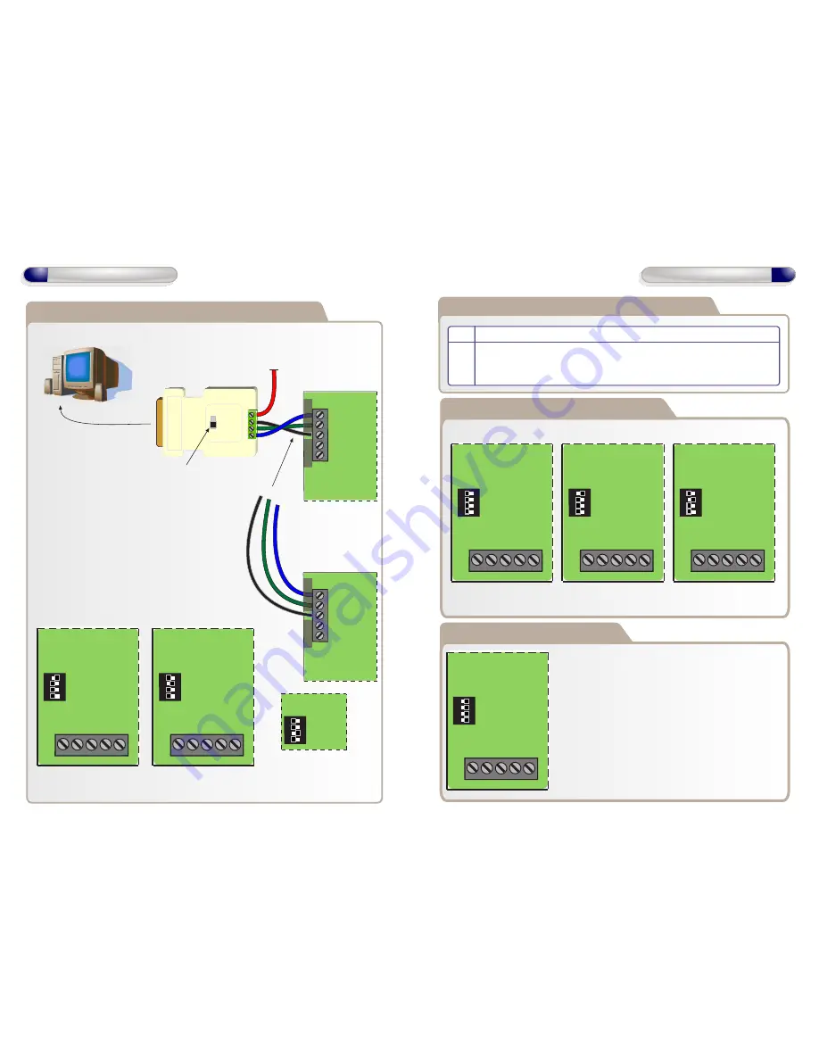
Network Diagrams for Multiple Controllers
19200
9600
12V - 1
0V - 2
B - 3
A - 4
A
B
0V
TX
RX
PC Direct
12V
Connect using RS232-RS485
cable to serial port on PC
PC Network Connections, when using more
than one GSD Controller.
Daisy chain the PC network A , B , 0V to each controller.
Set an individual address for each controller
between 1 & 3 using the dip switches
(see below )
RS485 Converter
A
B
0V
TX
RX
PC Direct
Controller 1
Controller 2
PC Network
Address 1 - Set SW1 ON Address 2 - Set SW2 ON Address 3 - Set SW3 ON
Controller 1
Controller 2
Set Baud Rate to 19200
Daisy Chain
each controller
A
B
0V
1 2 3 4
Controller 3
OFF
ON
1 2 3 4
IP4
IP3
0V
IP2
IP1
OFF
ON
1 2 3 4
IP4
IP3
0V
IP2
IP1
OFF
ON
Setting the GSD Controller address
Direct Connect - All OFF Address 1 - Set SW1 ON Address 2 - Set SW2 ON
Note: Address 3 - Set SW3 ON only
The Controller Address is set by configuring the Dip switches as shown below.
Configuring GSD Controller Communications
OFF
ON
1 2 3 4
IP4
IP3
0V
IP2
IP1
OFF
ON
1 2 3 4
IP4
IP3
0V
IP2
IP1
OFF
ON
1 2 3 4
IP4
IP3
0V
IP2
IP1
11
Network Diagrams
Restoring Factory Settings
Example: All Dip Switches are set to the ON position.
To restore the factory default setting , Set
ALL
Dip
Switches 1,2,3 & 4 to the ON position and then
power-up the GSD Controller.
OFF
ON
1 2 3 4
IP4
IP3
0V
IP2
IP1
Note: Factory Default settings will be restored after
powering up the controller with All dip-switches ON. The
dip-switches should then be set to the controller
address as shown above in section “Setting the GSD
controller address”
Step Description
1. On the “Controller” tab, set the “Connection - Type” to “Serial”
2. On the “Settings” tab in the communications section, Select the Serial Port
number from the drop-down list connected to the Controller.
PC Network


