background image

Factory Default PIN codes

The following PIN codes are the Factory Default Settings:

- User PIN ‘1111’ will grant access on door 1
- User PIN ‘2222’ will grant access on door 2

- The Default Engineer code is ‘6666’

Note: These User PINs (’1111’,’2222’) are deactivated when the first User PIN
is added to the keypad.

2

Operation Instructions

Technical Specs

Power Supply


12 - 24V AC or DC

Current consumption    

100mA

Current consumption with load (max)

130mA

Relay Contact Rating

5 Amps /240V ac

Operating Temperature

- 20  C   to +60  C

Moisture Resistance   

IP 67

Dimensions  - Flush Mount


W. 87mm D. 21mm H. 119mm

       - Surface Mount  

W. 87mm D. 35mm H. 119mm

Number of Users 

1000

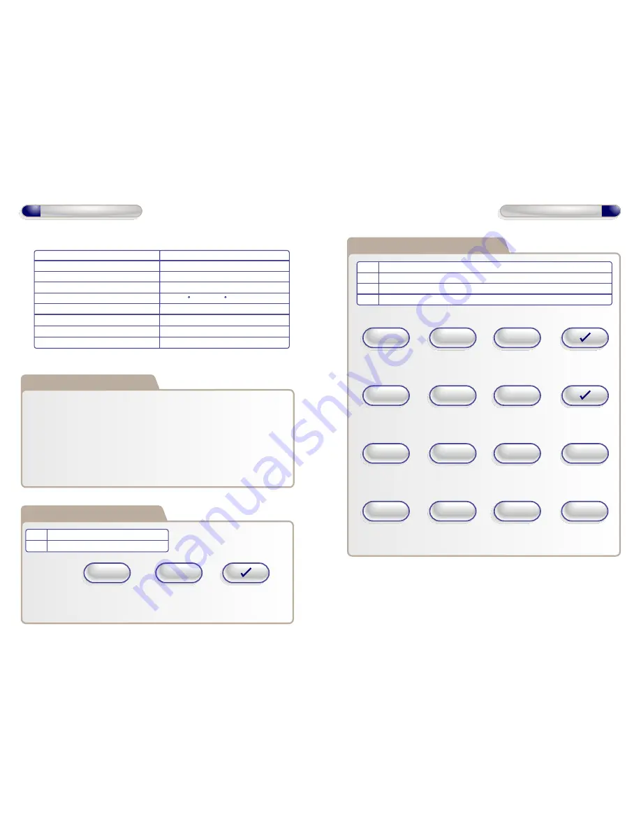
Restoring Factory Settings

Code    Description
  55      Restore Factory Default Settings

Example:

X key then

Engineer

Code

+

+

Code = 55

Note: If Engineer code is lost, Remove the Security Caps (see page 11) and

hold down the X key during power-up and enter the default Engineer

code ‘6666’ immediately. This will restore the factory settings.

3

Operation Instructions

Example: To Add User PIN ‘5656' to Door 1..

Example: To Remove User PIN ‘4545’ from any door..

Example: To Add Toggle User PIN ‘1234’ to Door 2..

Example: To Add Manager User PIN ‘5678’ to Door 2..

Adding and Removing User PINs

Code    Description
  01     Add a Standard User/Toggle User/Manager User PIN to Door 1
  02     Add a Standard User/Toggle User/Manager User PIN to Door 2
  03     Remove any User PIN

X key then

Engineer

Code

+

+

Code = 01

+

PIN = 5656

X key then

Engineer

Code

+

+

Code = 03

+

PIN = 4545

X key then

Engineer

Code

+

+

Code = 02

+

X key then

Engineer

Code

+

+

Code = 02

+

PIN = 5678

PIN = 1234

1

2

1 = Toggle User

2 = Manager User

Summary of Contents for 2 Door Pin and Proximity

Page 1: ...generation in access control solutions It provides a Wireless Network throughout the premises giving the convenience and security of a fully networked system for a fraction of the cost For more infor...

Page 2: ...55 Restore Factory Default Settings Example X key then Engineer Code Code 55 Note If Engineer code is lost Remove the Security Caps see page 11 and hold down the X key during power up and enter the de...

Page 3: ...in batch X key then Engineer Code Code 04 2 5 Operation Instructions Adding User Cards or Fobs using Keypad Code Description 06 Add Batch of Cards using Keypad Door 1 46 Add Batch of Cards using Keyp...

Page 4: ...01234 PIN 4444 2 7 Operation Instructions Removing a Batch of Cards or Fobs Code Description 05 Removing a Batch of Cards Example To remove a Single Card Example To Remove a Batch of Cards Present Car...

Page 5: ...on on off Off 21 Set Ajar Alarm on off On 22 Set Guest Button on off On 23 Set Duress codes on off Off 24 Set Toggle Relay on off On 25 Set Door Forced Alarm on off On 26 Set Anti Tail Gate on off Off...

Page 6: ...ws provided Both Security Caps are then clipped onto keypad To attach Security Caps hook tabs into holes and push on Surface Mounting 11 Installation Diagrams To release Security Caps push a screwdriv...

Page 7: ...Interlock IP on 2nd Door Interlock IP from Interlock OP on 2nd Door NC2 COM NO2 IP3 OP2 Volt Free Tamper Contacts 1 and 2 Volt Free Tamper Contacts 1 and 2 12V Interlock Connections for Door 1 24 36V...

Page 8: ...Contact 0V Sounder 12V Linear Power supply 0V Common OV from the Fire Alarm Panel and the OV from the Keypad to avoid any ground loop issues NC2 COM NO2 IP3 OP2 Volt Free Tamper Contacts 1 and 2 12V D...

Reviews: