background image

EN

GLISH

51

Additional Information for units sold in the UK.

Units sold in the UK are suitable for operation from a 240V ac, 50Hz
mains supply.
The range of multi-system receivers is built to work in most European
countries. However, the mains plug and socket system for the UK differs
from many European countries.
This appliance has been supplied with a fitted, non-removable, approved
converter plug for use in the UK. This converter plug is fitted with a 5A
rated fuse.

In case this appliance is supplied with a moulded 2-pin Euro plug only,
which is unsuitable for UK operation, this must be cut off and immediately
disposed of. An approved 13A, 3-pin UK plug should then be fitted by a
qualified electrician.

Note:

The severed Euro plug must be destroyed to avoid a possible
shock hazard should it be inserted into a socket elsewhere.

If a non-rewireable 3-pin plug or a rewireable 13A (BS1363) 3-pin plug
is used, it must be fitted with a 5A ASTA or BSI approved BS1362 fuse. If
any other type of plug is used it must be protected by a 5A fuse either in
the plug, or at the distribution board. If this type of plug becomes defec-
tive, ensure that the fuse is removed before disposal, to eliminate poten-
tial shock hazard.

If it is necessary to change the fuse in the non-rewireable plug, the cor-
rect type and rating (5A ASTA or BSI approved BS1362) must be used
and the fuse cover must be refitted. If the fuse cover is lost or damaged,
the lead and plug must not be used until a replacement is obtained. Re-
placement fuse covers should be obtained from your dealer.

Important:

The wires in the mains lead are colour coded in accordance with the fol-
lowing code:
BLUE – NEUTRAL
BROWN – LIVE
As the colours of the wires in the mains lead of your appliance may not
correspond with the coloured marking identifying terminals in your plug,
proceed as follows: 

Connect the BLUE coloured wire to plug terminal marked with the letter
“N” or coloured black.
Connect the BROWN coloured wire to the plug terminal marked with the
letter “L” or coloured red.
In no circumstance must any of the wires be connected to the terminal
marked with the letter “E”, earth symbol “

V

”, coloured green, or green &

yellow.

INFORMATION

------------------------------------------------------------------------------

Summary of Contents for VISION 7 47-7851 T

Page 1: ...COLOR TELEVISION VISION 7 47 7851 T...

Page 2: ...EVISION OPERATION 20 Basic functions 22 Zap function 22 Electronic TV guide 23 Changing the picture format 24 PIP mode 25 Remote control information 26 TELETEXT MODE 26 TOP text or FLOF text mode 26 N...

Page 3: ...d 41 SPECIAL SETTINGS 41 Tuning digital television stations 42 Tuning analogue television stations 44 Changing stored channels for analogue stations 47 INFORMATION 47 Displaying signal information 48...

Page 4: ...gerous and shortens the operating life of the television set For reasons of safety have a specialist remove any dirt deposits in the set from time to time Do not open the television set under any circ...

Page 5: ...her equipment while the device is switched on Switch o the other equipment as well before connecting it Only plug the device into the mains socket after you have con nected the external devices and th...

Page 6: ...control buttons are explained Receiving digital stations To receive digital stations you need a digital rooftop or indoor an tenna passive or active indoor antenna with its own power supply Unlike an...

Page 7: ...door antenna you may have to try it out at di erent positions until you get the best reception 2 Plug the mains cable supplied into the AC IN mains socket of the television 3 Plug the mains cable into...

Page 8: ...evision no longer reacts properly to remote control commands the batteries may be at Be sure to remove used batteries The manufacturer accepts no liability for damage resulting from used batteries Env...

Page 9: ...or PC CI Common Interface slot PC IN VGA VGA socket video signal input for PC COMPONENT INPUT Y Pb Pr Video signal input YUV signal AUDIO IN LR Audio signal input YUV signal SPDIF OUT Audio output soc...

Page 10: ...ns the pre selection for AV channels Press or V in the menu con rm with or M Opens the main menu Select the menu item with or V activate the function with or set the function with or switch o the menu...

Page 11: ...ects stations step by step moves the cursor in the menus up and down OK Calls up the channel list activates various functions Adjusts the volume moves the cursor left right TXT Switches between telete...

Page 12: ...on within 10 seconds the remote control returns to television mode TV Note DR has been programmed for operating a GRUNDIG digital receiver remote control level 1 DVD has been programmed for operating...

Page 13: ...on if the an tenna is actually an active indoor antenna with a signal ampli er and it is not already supplied with a voltage via a mains plug or similar supply Otherwise you may cause a short circuit...

Page 14: ...G 3 Select Program Management with V or and con rm with G The PROGRAM MANAGEMENT menu is displayed Moving channels to di erent presets 1 In the PROGRAM MANAGEMENT menu press V S or P to select the cha...

Page 15: ...pears in the Lock column 4 Press i to end the setting Notes To enable the television channel press V S or P to select the channel in the PROGRAM MANAGE MENT menu Press to switch to the Lock display co...

Page 16: ...ou can enter the same channel in more than one favourites list Note You can delete channels from the favourites list Press V or to select the channel press or to switch to the favourites list 1 to 4 a...

Page 17: ...Dynamik Contrast backlighting adjusts according to the pic ture content to ensure optimum contrast MPEG Artefacte Reducion reduces any interference from arte facts pixel blocks from digital stations...

Page 18: ...d adjust the setting with or Stereo width Widens the audio output for stereo programmes and improves the sound with mono reception 1 Select Sound Mode with V or 2 Press or to select the setting Spatia...

Page 19: ...ted Equaliser The equaliser o ers you four preset sound settings Music Sport Cinema and Speech and one which you can create yourself User 1 Select Equalizer with V or and con rm with G The EQUALIZER m...

Page 20: ...ions from various lists e g All FAV1 1 Press P to call up the overview of channel lists The overview is displayed 2 Press V or to select the channel list and G to con rm Selecting AV channels 1 Call u...

Page 21: ...d picture setting from User Natural Soft or Rich with z You can alter the User picture setting see the Picture settings chapter on page 17 Sound settings You can select various audio settings when wat...

Page 22: ...l stations supply provide a detailed TV guide Many broadcasters supply the daily programme but no detailed descriptions There are broadcasters which do not provide any information at all 2 Select the...

Page 23: ...l sources from a set top box on the Euro AV socket the picture lls the screen completely and with the correct geometry 4 3 format The picture is shown in 4 3 format Cinema format The cinema setting is...

Page 24: ...een double window function presets 1 Select the picture source DVD player video recorder SAT re ceiver with V or Selecting the widescreen and left screen double window function presets 1 Select the pr...

Page 25: ...ble window 1 To quit the double window press PIP Remote control information You can view the remote control on the screen and check all the functions for the buttons 1 View the remote control by press...

Page 26: ...ext mode Normal text mode 1 Press TXT to switch to teletext mode 2 You can directly select teletext pages with 1 0 To return to page 100 press i 3 Press V to scroll back a page 4 Press to scroll to th...

Page 27: ...e sub page directly or press z red to go back one sub page or press green to go forward one sub page 3 Press S to quit the function Reveal answer Certain teletext pages contain hidden answers or infor...

Page 28: ...and press G to con rm 2 In the Time Adjustment menu item press or to select Manual 3 Select Time Zone with V or in Germany 1 00 hour 4 Set the time zone with or 5 Press i to end the setting Selecting...

Page 29: ...elect Start Time with V or Enter the start time in four digits with 1 0 6 Select the End Time with V or Enter the switch o time in four digits with 1 0 7 Select Repeat with V or If required select the...

Page 30: ...3 yellow 3 Select Channel number with V or then enter television channel with 1 0 and con rm with 3 yellow 4 Press i to end the setting Note The switch on time can be deleted with z red Changing the m...

Page 31: ...or 2 Activate the lock with or 3 Select Parental Rating with V or 4 Press or to select the access level 5 Press i to end the setting Locking the keypad If the keypad lock is activated the buttons on t...

Page 32: ...i The PICTURE menu appears 2 Select the FEATURES menu with V or and press G to con rm 3 Select Software Update with V or and press G to con rm The current software is displayed in the Latest version m...

Page 33: ...ive Subtitle Setting with V or 3 Press or to make the setting 4 Press i to end the setting Restoring the television to its original state This function enables you to delete the channel lists and all...

Page 34: ...er you have connected the external devices High de nition HD ready Your television can playback high de nition television signals HDTV You can connect the input sources HDTV set top box or High De nit...

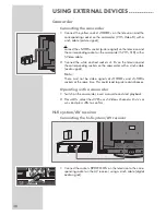
Page 35: ...ART1 or SCART2 1 Connect the AV1 or AV2 socket on the television and the corresponding socket on the external device using a EURO AV cable video and audio signal using the SCART socket S Video signal...

Page 36: ...lect the input signal channel with or V SCART1 SCART2 SCART2 SV S Video CVBS YPbPr HDMI1 HDMI2 or HDMI3 and press G to con rm Headphones Connecting the headphones 1 Plug the headphone jack 3 5 mm jack...

Page 37: ...cting a decoder or satellite receiver 1 Connect the AV1 socket on the television set and the appro priate socket on the decoder using a EURO AV cable Using a decoder or satellite receiver 1 Switch on...

Page 38: ...the corresponding sockets on the camcorder with a cinch cable audio signal Note There must not be video signals at VIDEO and S VHS sockets at the same time This could lead to picture disturbances Oper...

Page 39: ...the PC channel with V or and press G to con rm Settings for the PC 1 Open the menu with i The PICTURE menu is displayed 2 Select the SETUP menu with V or and con rm with G 3 Select the function or set...

Page 40: ...u with i The PICTURE menu is displayed 2 Select the FEATURES menu with or and con rm with G 3 Select the Digital Features menu with or and con rm with G 4 Select CA Module with V or and press G to con...

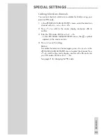
Page 41: ...amage your antenna 5 Select Auto tuning with V or and con rm with G 6 Select the Search Type with V or Press or to select the Digital display 7 Select Start Auto Search with V and con rm with G 8 Sele...

Page 42: ...television stations Note Plug the rooftop antenna cable for analogue television stations into the TUNER socket on the television 1 Open the menu with i The PICTURE menu appears 2 Select the SETUP men...

Page 43: ...stations repeat steps 4 to 7 8 Press i to end the setting Fine tuning analogue television stations The television automatically tunes itself to the best possible recep tion You may need to ne tune it...

Page 44: ...eleted and press 3 yellow to con rm 2 Press green to con rm the deletion Note Press z red to delete all the channels Sorting television channels 1 In the PROGRAM MANAGEMENT menu select the channel to...

Page 45: ...e Lock display and press G to con rm 3 Enter the PIN code 0000 with 1 0 In the PROGRAM MANAGEMENT menu the D symbol appears in the Lock column 4 Press i to end the setting Notes To enable the televisi...

Page 46: ...hannel with or into the favourites list 1 to 4 and save it with G The position in the favourites list is marked with You can enter the same channel in more than one favourites list Note You can delete...

Page 47: ...quency modulation quality and signal strength Notes The lower section of the menu shows the signal properties The further the bar for Quality and Signal Strength extends to the right the better the re...

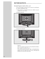
Page 48: ...front down on a table on top of a suitable base such as foam 2 Remove screw A 3 Remove the stand B Caution Follow the assembly instructions for the wall bracket carefully or have a specialist assemble...

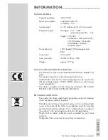
Page 49: ...s 2006 95 EG directive for electrical equipment to be used within de ned voltage ranges 2004 108 EG directive on electromag netic compatibility The device complies with the following standards EN 6006...

Page 50: ...setting if setting option is available Problem at station Volume set to minimum Problem at station Television station has no tele text or antenna system Station signal too weak No optical connection R...

Page 51: ...g is used it must be protected by a 5A fuse either in the plug or at the distribution board If this type of plug becomes defec tive ensure that the fuse is removed before disposal to eliminate poten t...

Page 52: ...Grundig Multimedia B V Atrium Strawinskylaan 3105 NL 1077 ZX Amsterdam http www grundig com...

Reviews: