Allgemeiner T
eil / Gener
al Section
RBX 1-RF
1 - 6
GR
UNDIG
Ser
vice
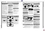
The RBX1-RF speaker is configurable for rear
surround and for stereo use.
Home cinema installation
– As a rear surround speaker, the RBX1-RF
should be positioned behind the listener in
the room and the centre speaker CLB in the
centre between both front speakers, e.g.
underneath or on top of the TV.
• Set the 2-position slide switch on the back of
the RBX1-RF to
SURROUND
.
• Select on the amplifier the DOLBY PRO
LOGIC mode.
– In this mode the audio signal of the speaker
is controlled by the amplifier/receiver and
the RBX1-RF does not react to its remote
control.
STEREO
SURROUND
MODE
SURROUND OR STEREO INSTALLATION
LEFT
RIGHT
TV
CENTRE
CLB
RBX1-RF
RBX1-RF
ROOM B
ROOM A
HOME CINEMA
STEREO
CLB
Multi-room installation
The RBX1-RF can also be used as a stereo
speaker in a second room.
– As a stereo speaker in another room, the
RBX1-RF can be positioned in front of the
listener. The ‘Space Fidelity’ concept of the
speaker provides a fantastic stereo sound
everywhere you go in the listening room.
• Set the 2-position slide switch on the back
of the speaker to
STEREO
.
• Make sure that normal STEREO or
3-CHANNEL mode is selected on the
amplifier.
– In stereo mode, you can control the active
speaker via the supplied remote control as
described on page 14.
NOTE:
the reach of the RF signal is 30 m in
open air. This distance will be reduced if
walls are in between, depending very much
on the construction materials.
STEREO
SURROUND
MODE
Switching the RBX1-RF on and off
You can switch the speaker on and off with the
POWER
button.
When the power is switched off, the set is separated from
the mains supply. (no power consumption).
The yellow
6
in the middle of the
POWER
button indicates
that the unit is on or in standby mode.
Stand by
In SURROUND mode:
In this mode the speaker is automatically activated when the
correct RF signals are received. The speaker is also
switched to STAND BY automatically if during 5 minutes no
RF-signals are received from the amplifier and remains in
standby until RF-signals are received again.
In STEREO mode:
You can switch the speaker to STAND BY with the
y
button
on the remote control. The speaker is also switched to
STAND BY automatically if during 5 minutes no RF-signals
are received from the amplifier.
When you want to switch your speaker on again, simply
press
y
on the remote control again.
Switching the speakers on and off on the
amplifier
SPEAKERS A
• Use the
SPEAKERS A
button to switch on and off the
speakers connected to the CENTRE SPEAKER and
SPEAKERS terminals and the rear speaker RBX1-RF (if set
to SURROUND mode).
RF
• The stereo RF transmission can only be switched on when
the amplifier is in normal stereo or in
3-CHANNEL mode.
In this mode, an RBX1-RF set to STEREO mode can
receive the stereo signal from the amplifier.
Note:
make sure that the CHANNEL selection is the same
on the amplifier and on the speaker.
OPERATING ELEMENTS
Front of the RBX1-RF
POWER
This button is used for switching the unit on and off. The yellow
6
in the middle of the button indicates that the unit is on or in standby mode.
OPERATE
6
This
6
is blinking, any time the set is not matched with the mode of the amplifier.
The 2-position slide switch on the back must be set to the correct mode (STEREO or
SURROUND) It also blinks if there are no RF signals received. On an audio session
this
6
is always on.
MUTE
6
This
6
is blinking any time the commands MUTE and SPEAKERS OFF are activated
or if there are no RF signals received. On an audio session this
6
is always on.
IR SENSOR
To receive signals from the supplied remote control (if RBX1-RF is set to STEREO mode).
Back of the RBX1-RF
2-position slide switch
STEREO/
This switch is used to select the desired mode of the RBX1-RF.
SURROUND
If set to SURROUND, the RBX-1 RF acts as a rear speaker in a Pro Logic system. In
this mode the audio signal is controlled by the RF-amplifier. The speaker does not
react to its remote control
If set to STEREO, the RBX-1 RF acts as a stereo speaker which can be placed in a
second room. In this mode, the audio signal can be controlled by the supplied remote
control.
7-position slide switch
CHANNEL
To select the RF reception channel (1–7). Make sure that the same channel is
selected on the speaker and the amplifier
Sound control via the remote control
Only when the RBX1-RF is set to STEREO mode
During reception of remote control signals the
OPERATE
6
is blinking.
VOLUME
The volume can be adjusted with the
–
keys.
MUTING
The volume can be completely muted by pressing the
s
button on the remote control. This is useful, for
example, if you want to take a telephone call and do
not want to be distracted by music, news, etc., from
your system. The
MUTE
6
starts blinking.
The MUTING function can be deactivated by pressing
s
again or by pressing the
key.
BASS, TREBLE
The
BASS +
/
–
and
/
–
keys can be used to
individually adjust the higher and lower frequencies
from the sound of your speaker. In this way, you can
compensate for surrounding acoustic irregularities which
may be caused, for example, by sound reflection be-
haviour on walls with relatively large, empty surface
areas, or "damping" caused by furniture or other objects.
DEFEAT
The
DEFEAT
switch can be used to deactivate any
bass and treble adjustment.
This function ensures that the original sound is
reproduced with the highest fidelity.
Changing the batteries
If the range of your infrared remote control seems to
decrease, or if certain individual functions can no longer
be carried out, you should replace the batteries.
Two micro 1.5 Volt LR03 size AAA are required. To
change the batteries, open the compartment on the back
of the remote control. Ensure that the batteries are in-
serted properly (note the markings in the compartment).
In the interest of the environment:
Remember that
batteries must always be disposed of properly.
SOUND CONTROL
RBX 1-RF
Nominal power.......................................2 x 25 W
Music power ..........................................2 x 45 W
Transmission range..........................40...15.000 Hz
Number of speakers.............................................4
Mid range type....................................105 mm
Tweeter type .........................................13 mm
Impedance .................................................4 Ohm
Volume approx. ..............................................7,1 l
Power supply
Voltage ...............................................230 V~
Frequency........................................50/60 Hz
Max. power consumption .......................125 W
Standby power consumption.....................< 5 W
Dimensions & weight
W x H x D.......................665 x 215 x 180 mm
Weight ........................................approx. 9 kg
CLB
Nominal power ............................................60 W
Music power................................................90 W
Transmission range..........................85...20.000 Hz
Number of speakers.............................................3
Mid range type....................................100 mm
Tweeter type .........................................20 mm
Impedance .................................................4 Ohm
Volume approx. ..............................................6,5 l
Dimensions & weight
W x H x D.......................430 x 125 x 175 mm
Weight ........................................approx. 4 kg
Accessories
.................................Instructions For Use
............................................................Ident card
.......................................................remote control
............................2 x 1.5V micro batteries size AAA
............................................Speaker cable for CLB
Subject to technical alterations and alterations in
styling E. and O.E.
TECHNICAL DATA
BASS
TREBLE
DEFEAT
VOLUME
Remote Control RC - LS 1
POWER
The following checklist will help you to correct most of the problems that can occur with your unit.
Before you go through the following list, verify if the mains cable (RBX1-RF) and the cables to the speaker (CLB) are securely connected.
If the following list does not help, please consult your HiFi dealer.
WARNING :
Under no circumstances should you try to repair the set yourself, as this would invalidate the guarantee.
Problem
Possible cause
Remedy
No sound.
VOLUME not adapted
Press
on the remote control (in STEREO mode)
Turn up the volume on the amplifier (in SURROUND mode)
RBX1-RF is not switched on
Switch on the RBX1-RF with the
POWER
button.
SPEAKERS A
/
SPEAKERS RF
on the amplifier not switched on
Press the
SPEAKERS A
and/or
RF
on the amplifier.
MUTING function switched on
Switch off the MUTING function
(
s
button on the remote control).
No sound, sound cuts
The RF channels selected on the amplifier and RBX1-RF
Select on both units the same RF channel
appear or
OPERATE
6
is
speaker do not match
blinking every second
The SURROUND/STEREO modes on amplifier and speaker
Select on both units the same SURROUND or STEREO
do not match
mode
The speaker is too far away from the amplifier or the RF-
Move the speaker nearer to the amplifier
signal is distorted by materials situated between the
speaker and the amplifier
The SPEAKERS RF is not switched on (STEREO mode only)
Press the
SPEAKERS RF
switch on the amplifier.
Sound interferences
Interferences from home security and car locking systems
Try to move the RBX1-RF to another position
Electromagnetic radiation from other electric or electronic equipment.
Select another RF channel both on amplifier and RBX1-RF
Poor sound
Excessive adjustment of the bass or treble tones
Press
DEFEAT
on the remote control
Adjust BASS and TREBLE to your personal taste
The RBX1-RF produces sound Interference from a neighbour transmitter
Select another RF channel on amplifier and speaker
from another sound source
The remote control does
Batteries empty
Replace the batteries.
not work.
The RBX1-RF is set to SURROUND mode and in this
The sound can be controlled by the amplifier or select
case the sound is controlled by the amplifier.
the STEREO mode on speaker and amplifier to be able to
use the remote control.
Too far away from the unit, or pointed at an excessive angle
Move nearer to the unit
Caring for the unit
• Wipe the housing clean with a soft, dry and antistatic cloth.
• Polishing and cleaning agents can damage the surface of the housing.
This unit meets the CEE regulations concerning interference radiation.
This unit complies with the safety regulations according to VDE 0860/BS 415 and thus with the international safety regulation EN 60065.
This product fulfills European directives 89/336/EEC, 73/23/EEC and 93/68/EEC.
TROUBLESHOOTING


