


Allgemeiner T
eil / General Section
R 23 DPL
1 - 6
GRUNDIG
Service
SYSTEM REMOTE CONTROL
Changing the batteries
If the range of your infrared remote control seems to
decrease, or if certain individual functions can no longer
be carried out, you should replace the batteries.
Two micro 1.5 Volt LR03 size AAA are required. To
change the batteries, open the compartment on the
back of the remote control. Ensure that the batteries
are inserted properly (note the markings in the
compartment).
In the interest of the environment:
Remember that batteries must always be
disposed of properly.
General controls
y
HIFI
– To switch the HIFI system to STAND BY.
/–
– Controlling the volume of the
amplifier.
a
– For muting the speakers.
SURROUND INST
This button is used to switch
between SURROUND and STEREO mode and to enter
the installation mode for surround settings.
REAR –
to call up rear level adjustment mode or to
manipulate the different surround settings
to call up centre level adjustment mode or
to manipulate the different surround settings
TUNER
TUNER
– For selecting the radio and to assign the RC
commands to radio keys.
10-button keypad
for directly selecting frequencies
$ #
STATION
– For selecting stations.
S T
– To start tuning up/down.
TXT/
6
– To change the information shown in the
display.
PTY
– For selecting the programme type (PTY) mode.
CD
CD
– For selecting the CD player and to assign the
RC commands to CD keys.
10-button keypad
for directly selecting tracks
;
– To switch the CD player to PAUSE.
9
– To switch the CD player to STOP.
B
– To start and restart playback of the CD player.
S T
– To select next or previous tracks on a
CD, to search forward and backward.
DISC
– To enter disc selection mode when using a
CD-changer.
TAPE
TAPE
– For selecting the cassette deck and to assign
the RC commands to TAPE keys.
B
– To start playback.
9
– To switch the cassette deck to STOP.
;
– To switch the cassette deck to PAUSE.
S T
– For fast winding of the tape in forward
or reverse direction or to search for next or previous
tracks during playback.
A B
– For selecting the tape travel direction.
TXT/
6
– This button is used for switching between the
COUNTER (tape counter) and TIME (real time in
minutes and seconds) display.
1
E
a
6
w
RADIO
TUNING TO RADIO STATIONS
RDS Radio Data System
R
Your receiver is an RDS receiver.
It is capable of receiving and evaluating RDS
information which is broadcast along with the
normal broadcast signal providing the listener
with more comfort and extra usefull information.
You can also call up other RDS services like RDS
time and radiotext provided that this information
is transmitted.(button
INFO
, see page 25).
RDS Station name :
If you are tuned to an RDS
station, the name of the station will be indicated
after a short time, overwriting names previously
stored.
RDS TIME :
Some RDS stations broadcast the
'RDS-TIME' information. The time display is
updated every minute. The accuracy of the time
depends on the broadcasted information.
RADIOTEXT :
More and more RDS stations
broadcast RADIOTEXT, which is additional
information on the station and programme being
broadcast. RADIOTEXT information appears as
"running" text in the display. RADIOTEXT is
transmitted character-by-character by the radio
station. As a result of that it may take some time
until the entire text has been completely received.
PROGRAMME TYPE :
Each station can broadcast
a code (PTY) that characterizes the actual
program. With the
PTY
button you can select the
type of programme you wish to listen to.
FM reception STEREO/MONO
Still, there are stations with disturbances or noise
in the audio signal, due to a weak signal.
• When the FM reception is disturbed, press
MONO
. Now the mono function will reduce
noise due to weak reception.
–
MONO
appears on the display.
Automatic tuning
• Press
TUNER
on the unit or remote control.
– The display shows the current frequency in the
FM waveband.
• To activate automatic station search, press
TUNING
#
or
$
until the frequency display
begins 'to run'; then release the button.
– The search stops as soon as a station with
sufficient reception quality is found.
–
TUNED
lights up when a station is tuned to precisely.
– The frequency of the received station is
indicated in
MHz
(FM).
– Stations which are received with a weak field
strength may be skipped. These can be tuned
to manually.
• If desired, you can also interrupt the search by
pressing
TUNING
#
or
$
.
Manual tuning
• Briefly press the
TUNING
#
or
$
button to tune
in the corresponding direction in individual
steps (FM: 50kHz) until the display shows the
right frequency and/or until the best reception
has been obtained.
Direct Frequency input
If you already know the frequency of the desired
station, you can enter it directly.
• Select
TUNER
on the remote control.
– The display shows the current frequency.
• Enter the desired reception frequency in order,
from left to right, by using the numeric buttons
0-9
on the remote control.
– After you have finished entering the last
number, your unit will receive the new station.
– You have 10 seconds to make each entry. If
this time limit is exceeded, you must enter it
again.
FM
97
MHz
FM
975
MHz
STEREO
TUNED
MHz
➥
➥
FM
9750
FM
9300
MHz
FM
9305
MHz
STEREO
TUNED
MHz
➥
➥
FM
9310
STEREO
TUNED
FM
8800
MHz
FM
8750
MHz
Storing Preset Stations
You can store up to 30 stations in the memory.
When a preset station is selected, the preset num-
ber appears next to the frequency on the display.
Automatic programming
•
Press
MEMORY
for more than 1 second.
–
MEMO
flashes on the display.
– Every available station will be stored automati-
cally. The frequency and preset number will be
displayed briefly.
– It will stop searching when all the available
stations are stored or the memory for 30 preset
stations is used.
– The set will remain tuned to the last stored
preset number.
• You can cancel the automatic programming by
pressing
MEMORY
again or any other key on
the unit.
Note:
If you want to maintain some old preset
numbers, for example preset number 1 - 9, select
preset 10 before starting automatic program-
ming: now only the preset numbers 10 to 30 will
be programmed.
Manual programming
•
Press briefly
MEMORY
for less than 1 second.
–
MEMO
flashes on the display.
•
Press
TUNING
#
or
$
to tune to the desired
frequency.
•
Press
STATION
#
or
$
to select a preset
number.
•
Press
MEMORY
again.
–
MEMO
stops flashing, and the station is stored.
• Repeat the above procedure to store other
preset stations.
STATION MEMORY
Calling up a stored station
• When you want to call up a stored station,
press
STATION
#
or
$
on the unit or on the
remote control.
– The stations are called up in ascending or
descending order.
Deleting all stored stations
• If you wish to delete all stored stations, for
example after you move to another location,
press first
MEMORY
.
–
MEMO
flashes on the display.
• Press now at the same time the buttons
TUNER
and
MEMORY
.
– All stored stations have now been cleared and
the display shows ‘
FREE
’.
Changing display indication:
• Pressing
INFO
on the unit or
TXT
/
6
on the
remote control briefly switches the display
mode between (when available) station name,
RDS-time, RADIOTEXT, and frequency.
MEMO
FM
8750
MHz
STEREO
TUNED
MEMO
PRESET
FM
9300
MHz
➥
RDS
RDS
RT
STEREO
TUNED
PRESET
➥
PTY
RT
STEREO
TUNED
PRESET
BAYERN 3
RDS
PTY
RT •
STEREO
TUNED
PRESET
ARD-RADI
PTY
13
45
RDS
PTY
RT
STEREO
TUNED
PRESET
FM
9790
MHz
➥
➥
➥
STEREO
TUNED
MEMO
PRESET
FM
9725
MHz
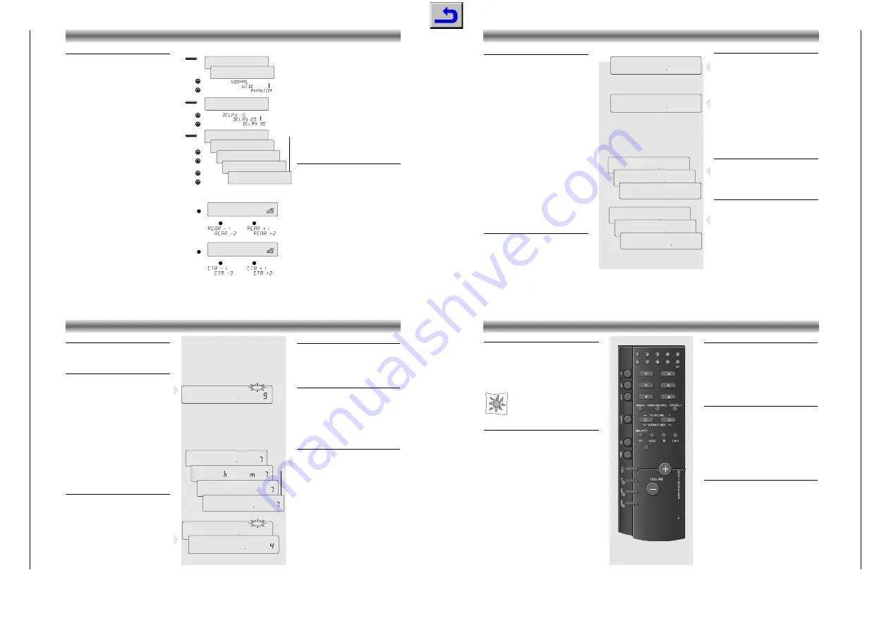
ADAPTING THE SURROUND MODE VALUES
Adapting the Surround mode values
The surround mode has programmed values for
centre-mode, centre and rear levels and for rear
channel time delay which are suitable for most
common applications.
You can , however, change these settings to your
particular taste or speaker installation.
To install your Surround system proceed as
follows:
• Select the Dolby Pro Logic mode.
• Press the
SURROUND
key longer than 2
seconds.
– The display shows e.g.‘
NORMAL
’.
• Use the
# $
(
TUNING
or
STATION
) buttons to
select the centre channel mode:
NORMAL
,
WIDE
or
PHANTOM
.
– Select
NORMAL
if you are using a normal
centre speaker.
– Select
WIDE
if you have connected a HiFi
centre speaker
– Select
PHANTOM
if you have not connected a
centre speaker, but still wish to simulate the
sound coming from the centre.
• Press the
SURROUND
button again.
– The display shows e.g.
DELAY 20
.
• Use the
# $
(
TUNING
or
STATION
) buttons to
adjust the delay time of the rear channel
(15, 20 or 30 ms).
Increasing the rear delay time expands the
perceived listening area, and vice versa.
• Press the
SURROUND
button again.
– You will now hear a test tone from the left,
centre, right and rear speakers in turn, in a
repeating cycle.
– The display shows e.g.
TEST FL
➡
TEST C
➡
TEST FR
➡
TEST R
➡
TEST FL
• The values of the centre and rear level can be
adjusted if you press
# $
(
TUNING
or
STATION
) during the 2 seconds that you hear
the test tone of the centre
TEST C
and the
rear speaker
TEST R
.
• When you are satisfied with the levels, press
the
SURROUND
button again to turn off the test
tone and leave the installation mode.
Note:
When you have selected
PHANTOM
for the
centre channel mode, the test tone sequence will be
as follows:
TEST FL
➡
TEST FR
➡
TEST R
➡
TEST FL
Direct adjustment of rear and centre level
During e.g. a film, it is possible that the special
effects on the rear speakers become too loud or
too quiet compared to the level of the dialogue,
making it necessary to perform small adjustments.
Your
remote control
is, for this purpose,
provided with two keys for direct adjustment:
Adjusting the rear level
• Press the
– REAR
button.
The display shows e.g.
REAR 0
.
• If you press within 2 seconds the
or
– REAR
buttons you can adjust the rear level
(related to the front level).
Adjusting the centre level
• Press the
button.
The display shows e.g.
CTR 0
.
• If you press within 2 seconds the
or
– REAR
buttons you can adjust the centre level
(related to the front level).
SURROUND
> 1.5 SEC
➥
➥
➥
➥
➡
➡
➡
➥
➥
➥
➥
➥
➥
➥
➥
SURROUND
SURROUND
PROLOGIC
VID 1
PRO LOGIC
TESTTONE
VID 1
PRO LOGIC
TEST FL
VID 1
PRO LOGIC
TEST C
VID 1
PRO LOGIC
TEST FR
VID 1
PRO LOGIC
TEST R
VID 1
PRO LOGIC
DELAY 15
VID 1
PRO LOGIC
NORMAL
VID 1
PRO LOGIC
TUNING / STATION
#
$
TUNING / STATION
#
$
TUNING / STATION
#
$
TUNING / STATION
#
$
➥
REAR
0
VID 1
PRO LOGIC
➥
REAR/–
REAR/–
➥
CTR
0
VID 1
PRO LOGIC
➥
REAR/–


