


Zusätzlich erforderliche
Unterlagen für den Komplettservice
Additionally required
Service Manuals for the Complete Service
Service
Manual
Btx * 32700 #
Sachnummer
Part Number 72010-757.20
Änderungen vorbehalten
Subject to alteration
Printed in Germany
VK231 0198
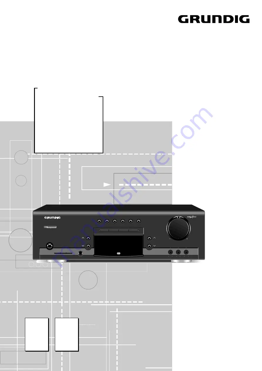
R 23 DPL
Sach-Nr./Part No.
72010-757.20
TV/SAT
VCR/LiveCam
HiFi/Audio
Car Audio
Telekommunikation
0180/52318-41
0180/52318-42
0180/52318-43
0180/52318-44
0180/52318-45