GRUNDIG Service
2 - 11
GV 54…, GV 56 …, SE 5106…
Beschreibungen / Descriptions
3. Family Board II (OKV++G)
3.1 Family Board II – Drive Control /
Deck Electronic (DE)
Function Overview
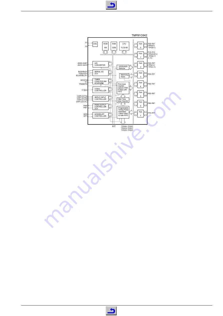
Deck control is effected by the deck
computer IC7100, TVC (Toshiba Video
Controller) together with the micro-
computer IC7120 on the keyboard con-
trol unit, and the central computer
IC7300 on the Family Board. Data
communication between the two mi-
crocomputers takes place via the bi-
directional serial interface DATA-S /
CLOCK-S.
The deck computer is a microcom-
puter especially developed for video
recorders. The operating system is
stored in the integrated mask-pro-
grammed ROM of the
µ
C. The com-
puting speed is determined by quartz
Q1190.
The deck computer is responsible for
driving and checking the tape deck
including the servo systems for the
tape transport and headwheel control.
It also controls the record/playback
switching process.
The tape deck control consists of the following function groups:
3.1.1
Threading motor control
(cassette compartment / threading mechanism)
3.1.2
Winding tachopulse processing
3.1.3
Tape start/tape end detection
3.1.4
Head servo control
3.1.5
Tape servo control
3.1.6
Tracking / autotracking
3.1.1 Threading Motor Control
(cassette compartment / threading mechanism)
The cassette compartment and threading mechanism is driven by the
threading motor. For driving the threading motor, the tape deck
computer IC7100 feeds out control signals for the sense of rotation at
Pin 35 and for the speed at Pin 10. These signals are used to drive the
threading motor via the threading motor driver IC7130-(5/6, 7/8) and
plug contact 1508-(1/3).
The
µ
C detects the position of the tape deck by counting the threading
tachopulses in connection with the INIT switch and the identification
"TS" for the beginning of the tape, and "TE" for the end of the tape. The
threading tachopulses are supplied to the
µ
C IC7100-(29) via plug
contact 1502-(6) and IC7080-(6/17). The tape deck is fitted with a
switch for initialisation of the threading tacho (INIT) and another for
erase protection (RECORD LOCK). The voltages resulting from the
switch settings are coupled via the plug contacts 1502-(3/7), R3043
(INIT) and R3045 (RECORD LOCK) and fed to the IC7100-(52).
The cassette compartment is mechanically connected with the thread-
ing tacho generator (vane wheel). When loading a cassette into the
cassette compartment the cassette must be inserted as far as is
necessary to generate three threading tachopulses. Afterwards, the
sequence control computer activates the threading motor which then
takes over the loading of the cassette.
When ejecting the cassette, the phototransistor detecting the begin-
ning of the tape is released mechanically a short time before the lift
reaches the end position. A short time later, the threading motor is
automatically switched off by the tape deck computer.
3.1.2 Winding Tachopulse Processing
The optocouplers on the left (WT1) and right (WT2) reels produce 8
pulses per revolution. These pulses are formed into rectangular
signals within IC7080 (pins 8/14 –> pins 7/15) and applied to
IC7100-(8/9). This IC calculates the instantaneous tape position and
the total length of the cassette from the ratio of these two frequencies.
3. Chassisplatte II (OKV++G)
3.1 Chassisplatte II – Laufwerksteuerung /
Deckelektronik (DE)
Funktionsübersicht
Die Steuerung des Laufwerks über-
nimmt der Laufwerksrechner IC7100,
TVC (Toshiba Video Controller) mit
dem Mikrocomputer IC7120 auf der
Bedieneinheit und dem Hauptrechner
IC7300 auf der Chassisplatte. Der
Datenaustausch zwischen den Mikro-
computern erfolgt über die bidirektio-
nale serielle Schnittstelle DATA-S /
CLOCK-S.
Der Laufwerksrechner ist ein speziell
für Videorecorder entwickelter Mikro-
computer. Das Betriebssystem ist im
integrierten maskenprogrammierten
ROM des
µ
Cs gespeichert. Die Rech-
nergeschwindigkeit legt der Quarz
Q1190 fest.
Der Laufwerksrechner übernimmt die
Steuerung und die Kontrolle des Lauf-
werks inklusive der Servosysteme für
den Bandvorschub und die Kopf-
scheibensteuerung. Des weiteren steu-
ert dieser die Aufnahme-/Wiedergabe-
umschaltung.
Die Laufwerksteuerung ist in folgende Funktionsgruppen unterteilt:
3.1.1
Steuerung des Fädelmotors
(Cassettenschacht / Fädelmechanik)
3.1.2
Wickeltachoimpulsverarbeitung
3.1.3
Bandanfang- / Bandende-Erkennung
3.1.4
Kopfservoregelung
3.1.5
Bandservoregelung
3.1.6
Trackingregelung / Autotracking
3.1.1 Steuerung des Fädelmotors
(Cassettenschacht / Fädelmechanik)
Der Antrieb der Cassettenschacht- und Fädelmechanik erfolgt über
den Fädelmotor. Zur Ansteuerung des Fädelmotors gibt der Laufwerks-
rechner IC7100 Steuersignale an Pin 35 für die Drehrichtung und an
Pin 10 für die Drehzahl aus. Mit diesen steuert man über den Fädel-
motor-Treiber IC7130-(5/6, 7/8) und Steckerkontakt 1508-(1/3) den
Fädelmotor.
Die Laufwerksposition erkennt der
µ
C durch das Zählen der Fädeltacho-
impulse in Verbindung mit dem Schalter INIT sowie der Kennung des
Bandanfangs "TS" sowie Bandendes "TE". Die Fädeltachoimpulse
werden über Steckerkontakt 1502-(6) und IC7080-(6/17) dem
µ
C
IC7100-(29) zugeführt. Das Laufwerk enthält je einen Schalter zur
Initialisierung des Fädeltachos (INIT) und zur Löschsicherung
(RECORD LOCK). Die Spannungen entsprechend der Schaltzustände
verkoppelt man über die Steckerkontakte 1502-(3/7), R3043 (INIT)
sowie R3045 (RECORD LOCK) und führt diese dem IC7100-(52) zu.
Der Cassettenschacht ist mechanisch mit dem Fädeltachogeber (Flügel-
rad) verbunden. Beim Einschieben einer Cassette in den Cassetten-
schacht muß diese soweit eingeschoben werden, bis drei Fädel-
tachoimpulse erzeugt wurden. Danach aktiviert der Ablaufrechner den
Fädelmotor und übernimmt somit das Laden der Cassette.
Beim Auswurf (Eject) der Cassette wird kurz vor Erreichen der Endpo-
sition des Cassettenschachtes der Empfänger für Bandanfangkennung
mechanisch freigegeben. Kurze Zeit später schaltet der Laufwerks-
rechner den Fädelmotor ab.
3.1.2 Wickeltachoimpulsverarbeitung
Die Optokoppler am linken und rechten Wickelteller (WT1 / WT2)
geben pro Umdrehung des Wickels 8 Impulse ab. Diese werden im
IC7080 (Pins 8/14 –> Pins 7/15) in Rechteckimpulse umgeformt und
dem IC7100-(8/9) zugeführt. Dieser errechnet aus dem Verhältnis der
beiden Frequenzen den augenblicklichen Bandstand und die Gesamt-
länge der Cassette.


