background image

Service 
Manual

Änderungen vorbehalten

Printed in Germany

Service Manual Sach-Nr.

Subject to alteration

VK 21/1   0895

Service Manual Part No.

72010-519.45

VIDEO

SERVICE MANUAL

D

 Btx 

*

 32700 

#

Service 
Manual

Sicherheit

Safety

Sach-Nr./Part No.

72010-800.00

Zusätzlich erforderli-
che Unterlagen
für den
Komplettservice:

Additionally required
Service Manuals for
the Complete Service:

GV 54…
GV 56…

SE 5106 …

Sach-Nr./Part No.

72010-519.45

GV 540 GB

(77400-617.51 / G.ME 3300 GB)

GV 540 HIFI

(77400-603.51 / G.ME 3000)

GV 540 NIC

(77400-608.51 / G.ME 3100)

(77400-659.51 / G.ME 3110)

GV 5695 HIFI 

/ Madrid

(77400-642.51 / G.ME 3900)

SE 5106 HIFI

(77400-638.51 / G.ME 2700)

GV 560 HIFI

(77400-601.51 / G.ME 3600)

GV 560 HIFI/LE

(77400-661.51 / G.ME 6300)

GV 560 NIC

(77400-609.51 / G.ME 3700)

(77400-662.51 / G.ME 3710)

%

TIMER

ON/OFF

%

e

e

%

TIMER
ON / OFF

%

1

2

3

4

5

6

7

8

9

SV

0

AV

SP/LP

ON/OFF

CLEAR

SET/CHECK

TIMER

SV/V+

PROG.

STOP

DAY

START

OK

+

+

-

0

9

3

6

8

7

5

2

1

4

AV

VPT

IN

D E

X

INDE

X M ARK

TR

AC

KI

NG

I

NDE X ER

ASE

RP540

(75988-010.73)

PAL / SECAM OST

GV 540 …
GV 560 …

GV 5695 … 

/ Madrid

SE 5106 …

%

TIMER

ON/OFF

%

e

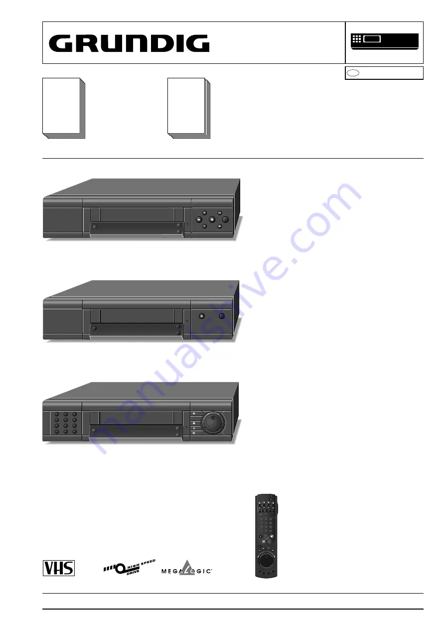
Summary of Contents for GV 540 HIFI

Page 1: ...19 45 GV 540 GB 77400 617 51 G ME 3300 GB GV 540 HIFI 77400 603 51 G ME 3000 GV 540 NIC 77400 608 51 G ME 3100 77400 659 51 G ME 3110 GV 5695 HIFI Madrid 77400 642 51 G ME 3900 SE 5106 HIFI 77400 638...

Page 2: ...Head Amplifier HC 4 69 Teletext Module DOS OVPTG VT 4 71 NICAM Decoder ONI NI 4 74 Keyboard Control Units ODCG DC 4 77 Oscillograms 4 93 Drive Mechanism 5 1 5 12 Test Equipment Aids 5 1 Service Instr...

Page 3: ...trol Unit II ODCG81 DC S P 4 83 Bedieneinheit I Keyboard Control Unit I ODCG8 DC 27599 002 48 S P 4 81 Bedieneinheit II Keyboard Control Unit II ODCG71 DC 75988 031 84 S P 4 77 Bedieneinheit I Keyboar...

Page 4: ...i Vor R cklauf mit E180 Cassette typisch 95s FS Norm CCIR B G H PAL CCIR I PAL CCIR B G SECAM Video Signal Rauschabstand Standard play 48dB bewertet Longplay 45dB bewertet Aufl sung 3 1MHz Ton Frequen...

Page 5: ...eicherte Videotext Seite am Bildschirm ein e W hlt Programmplatz A1 A 2 oder CV f r die Aufnahme bzw f r die TIMER Programmierung h Schaltet auf die Info Tafel und zur ck auf das Fernsehbild C Cursor...

Page 6: ...t gliche oder w chentliche Aufnahme bei der TIMER Programmierung SP LP CLEAR LP CL SL LP Schaltet auf Langspiel Betrieb und wieder zur ck auf Standardspiel Betrieb CL L scht TIMER Daten 7 Einstellung...

Page 7: ...mit Fernseh Programmen von der Antenne Kabelanschlu oder vom Satelliten belegt werden k nnen Die M glichkeiten zum Einstellen der Fernseh Programme 1 Durch die bernahme der Daten vom Fernseh ger t Da...

Page 8: ...en DC E F anw hlen Programmplatz mit Taste Z ED EW gr n markieren Neuen Programmplatz mit den Tasten DC anw hlen Die Daten des markierten Programmplatzes wer den an den neuen Programmplatz verschoben...

Page 9: ...equenz Kanal Eingabe W hlen OK Best tigen TV Bild i Zur ck zum INFO Men Programm 12 GRUNDIG TEXT PROGRAMMING Prog Kanal Sender VPT k 11 06 ARD 304 150 12 34 ZDF 304 150 13 59 BR 3 304 150 14 40 RTL 30...

Page 10: ...f r fremdbespielte Cassetten Wenn bei der Wiedergabe von fremdbespielten Cassetten das Bild springt oder durchl uft dr cken Sie nacheinander die Taste CODE die Ziffern Tasten 8 5 1 1 und Taste G Kurz...

Page 11: ...it dieser Fernbedienung k nnen verschiedene GRUNDIG Videorecorder unabh ngig voneinander bedient werden Ihren GV 560 und einen zweiten Videorecorder der Serie VS 600 bis VS 900 und ab der Serie GV 200...

Page 12: ...e search during playback rewind on stop Jog rotary disk Shuttle ring Flap right Level control indicator left Insert editing Switches over to headphone operation Switches over to manual record level co...

Page 13: ...g During TIMER programming dis plays the teletext page stored in the TV station table e Selects programme position A1 A2 or CV for recording or for TIMER programming h Switches to the info table and b...

Page 14: ...NDIG TEXT PROGRAMMING 10 CNN 01 15 00 16 30 Enter timer data VPS PDC On Off ED EW Normal LP CL Long Play Clear timer CHECK next timer i Return to Info menu Timer Prog Date Start Stop dialogue lines 7...

Page 15: ...There are 99 programme positions available You can assign them as you wish to TV stations from the aerial a cable connection or a satellite A number of options are available for tuning 1 By transfer o...

Page 16: ...on using the DC E F buttons Mark programme position with the Z ED EW green button Select new programme position with the DC but tons The data for the marked programme position are transferred to the n...

Page 17: ...uning 3 Teletext page 301 Subtitle page 320 0 9 Enter channel search Special channel On Off Frequency Channel Input Select OK Confirm TV Picture Programme 12 GRUNDIG TEXT PROGRAMMING Prog Channel Iden...

Page 18: ...order If the picture jumps or scrolls when playing back tapes recorded on another recorder press the CODE button the numbered buttons 8 5 1 1 and the G button one after another Brief display on the re...

Page 19: ...fferent GRUNDIG video recorders can be opera ted independently of one another using this remote control Your GV 560 and a second video recorder from the VS 600 to VS 900 series and from the GV 200 ser...

Page 20: ...wo for each flap in the direction of the arrows Fig 2 Open the front flaps halfway and remove them Servicehinweise 1 Entfernen der Geh useteile 1 1 Geh useoberteil 5 Schrauben A herausdrehen Fig 1 Sei...

Page 21: ...drehen Fig 8 Jog Shuttle Drehkn pfe abziehen und Bedieneinheit II abnehmen 2 2 Chassisplatte ausbauen 2 Schrauben L herausdrehen Fig 6 Rastnasen M l sen und Chassisplatte herausnehmen Fig 6 Gegebenenf...

Page 22: ...U Fig 13 zug nglich sind Schrauben U entfernen Fig 13 und gegebenenfalls Steckverbin dungen zur Elektronik l sen 2 4 Removing the NICAM Decoder Press the guides N carefully apart and take out the NIC...

Page 23: ...und Oszillogramme Bei den in den Schaltpl nen und Oszillogrammen angegebenen Me werten handelt es sich um N herungswerte 3 WARNING Chassis Connections When re assembling the machine it is strictly to...

Page 24: ...roduction code and the serial number on the code label of the drive mechanism do not necessarily agree with the production code and the serial number on the type plate Laufwerks Codeaufkleber Hinweis...

Page 25: ...status Level 3 Tape deck sensors and operating hours meter The levels can be changed step by step by pressing the TIMER ON OFF button on the recorder Level 3 is again followed by Level 1 Terminating t...

Page 26: ...eading tacho FG capstan motor PG FG headwheel motor When one tacho pulse is missing during the operation of the tape deck the VCR tries to move the cassette compartment to the EJECT position 1 3 Ebene...

Page 27: ...ced the video recorder must be realigned see Adjustment chapter 3 1 5 Erasing the Customised Data Warning This function erases all customised data clock time station table timer data The specific data...

Page 28: ...fehle werden angenommen 8546 Teletext ohne Zeilensprung 312 312 f r Fernsehger te mit 50Hz Bildwechselfrequenz 8547 Teletext mit Zeilensprung 312 313 f r Fernsehger te mit 100Hz Bildwechselfrequenz 85...

Page 29: ...ypical Data Mains voltage 220 240V Mains frequency 45 65Hz Maximum power 40W Switching frequency 30 120kHz Efficiency 80 at maximum load Short circuit protection provided for all outputs Principle of...

Page 30: ...transformer the voltages at the secondary windings fall below 0V These zero passages are detected by IC7010 at Pin 8 The transistor T7040 is switched on again and the next cycle is started Control of...

Page 31: ...ine 64kByte Adressierung zu Mit der Adresserweiterung Bank Switching IC7300 10 ist die Adressierung von bis zu 512kByte m glich Damit auf das EPROM zugegriffen wer den kann ist an IC7300 50 EA Massepo...

Page 32: ...re a stabilized 12V supply to operate This voltage is derived from the 14VA voltage of the power supply unit by means of T7210 T7215 IC7225 and T7220 and is then available as 12VD unswitched voltage F...

Page 33: ...of the left and right audio channels at IC7300 1 2 are evaluated to supply data to the automatic level control of audio IC7010 via the I2 C bus This data is also used to drive the level control indica...

Page 34: ...4 zugef hrt Beide Signale durchlaufen anschlie end je einen Synchrondemodulator mit nachfolgendem Verst rker und ge langen ber IC7520 10 11 zum Stereodecoder IC7570 7 8 Mono Ton Bei Monosendungen ist...

Page 35: ...ie Buchse EURO AV1 und den Matrixschalter IC7770 zum T7865 Beide Signale werden danach addiert und zum Pin 2 des Komparators IC7875 geleitet Der Komparator IC7875 vergleicht die addierten FBAS Signale...

Page 36: ...Bedienteilrechner die Aussteuerungsan zeige auf der Bedieneinheit 2 4 Family Board Audio AU TheAudiocircuitsectionprocessestheaudiosignalsforbothhelicalscan FM sound and longitudianl recording Standa...

Page 37: ...ch dem R P Schalter IC7010 29 28 und der Stummschaltungsstufe M wird es den Ausgangswahlschaltern im FM Ton Schaltungsteil zugef hrt Bei LP Wiedergabe bewirkt ein Schalter im IC7010 und der Konden sat...

Page 38: ...he V Impuls verf gbar ist 2 5 Family Board OSD Module OOSDG OS General The IC7900 makes it possible to display a full page with separate background Full Page and to insert information into the playbac...

Page 39: ...to rectangular signals within IC7080 pins 8 14 pins 7 15 and applied to IC7100 8 9 This IC calculates the instantaneous tape position and the total length of the cassette from the ratio of these two f...

Page 40: ...d die Autotracking Funktion abgeschaltet und die ermittelte Phasenlage ber die CTL Impulse geregelt 3 1 3 Tape Start Tape End Detection To identify the beginning of tape and end of tape the VHS casset...

Page 41: ...Pin 43 des IC7500 Bei VHS Wiedergabe f hrt man das FM Signal einem Bandpa Peakingkreis C2310 C2313 R3313 L5310 C2315 zu Die Resonanzfrequenzenbetragen9MHz Sperresonanz und5MHz Flu resonanz Nach der f...

Page 42: ...ignal 4 43MHz isfedthroughanR P switchtotheintegrated chroma bandpass FSC BPF On one path the signal is then taken via IC7500 19 and IC7540 2 directly to the comb filter in IC7540 On Im IC7500 teilt s...

Page 43: ...z Dieserwird berdeninternenBandpa SUBBPF demHauptmischer MAIN CONV zugef hrt another path it is additionally inverted for PAL NTSC and passed on via the MESECAM switch IC7500 17 and IC7540 4 to the co...

Page 44: ...rt 3 3 Family Board II Head Amplifier HC Function Overview On record the head amplifier has the task of feeding the video and audio signals to the rotating transformers The signals are then recorded o...

Page 45: ...4 Teletext Module DOS OVPTG VT Function Overview The DOS unit contains a Test Pattern Data Generator and the VPS PDC Teletext processing stage For this the following function groups ICs are required I...

Page 46: ...Encoder is switched at half the line frequency For this the frequency FH 2 burst phase from the Chroma circuit section of Family Board II OKV G is supplied to the transistor T7010 it is amplified conv...

Page 47: ...tein erh lt den LOW aktiven CAM RESET vom Bedienrechner IC7120 der bei Bedarf vom Hauptrechner IC7300 ausgel st wird Die Versorgungsspannung des IC7080 betr gt ca 4 7V und die Takt frequenz 10MHz legt...

Page 48: ...ber die Klinkenbuchse am Port P60 des IC7080 von LOW auf HIGH und an P01 INP1 ber T7085 von HIGH auf LOW SYNCHRO EDIT Control via Panasonic DC Control By reading in the levels at the ports P30 and P0...

Page 49: ...the analog input CIN0 of the keyboard control computer When no button is pressed the voltage at CIN0 is 0V When pressing the buttons the following voltages are supplied correspondingly T24 5V T25 4V...

Page 50: ...von Port P15 ber die Inverterstufe T7087 ebenfalls LOW aktiv angesteuert The ten buttons 21 23 Keyboard Control Unit I and 29 35 Key board Control Unit I II are arranged in a matrix The keyboard is ex...

Page 51: ...DE dr cken Im Display erscheint CODE Zahlenfolge 4 9 3 7 eingeben und mit Taste G best tigen Testcassette einlegen Servicefunktion mit dem Fernbediengeber aufrufen Taste CODE dr cken Im Display ersche...

Page 52: ...er t einspeisen EE Betrieb SendernormtestbildohneAudio Modulation UHF Bereich K26 Antennenpegel 67dB V in betriebswarmes Ger t einspeisen Oszilloskop MP 83 EE Betrieb Sendernormtestbild mit Tonmodulat...

Page 53: ...ern BIAS erh hen Taste 9 dr cken Im Display erscheint rechts A9 Nach dem erfolgreich durchgef hrten Abgleich schaltet das Ger t auf Standbild Sollte nach dem Abgleich der Spannungswert um mehr als 1dB...

Page 54: ...FM Referenz pegeleinstellung f r ACC Automa tic Contour Control plus Studio Quality 3 S VHS PB Detektion Referenzpegel S VHS R3409 REFS VHS R3481 REFV 4 PAL Chroma Aufsprechstrom R3363 CAP 5 Teletext...

Page 55: ...e Function with the remote control Press the CODE button CODE is indicated in the display Enter4937inthisorderandconfirmwithbuttonG Insert a test cassette Call up the Service Function with the remote...

Page 56: ...ltage to 2 5V 0 1V With R3540 AGC ADJ adjust the amplitude to 100mVpp Remove the 4 7pF capacitor With R3613 CHR ADJ set the burst amplitude to the level of the sync pulses Set the crosstalk to minimum...

Page 57: ...ndicated on the right of the display On successful completion of the adjustment the VCR switches to still If the voltage difference between HiFi and Standard Sound is more than 1dB after this adjustme...

Page 58: ...erence Level for ACC Automatic Contour Control plus Studio Quality 3 S VHS PB Detection Reference Level S VHS R3409 REFS VHS R3481 REFV 4 PAL Chroma Writing Current R3363 CAP 5 Teletext DOS OVPTG VT T...

Page 59: ...ten sondern vorgesehen X oder variantenbezogen sind Y Die variantenbezogenen Bauteile sind den Featu res zugeordnet siehe Feature bersichten U WR A SchaltspannungbeiAufnahme Switchingvoltageforrecord...

Page 60: ...entification de principio o fin de cinta Begin band einde band detectie U THR Einf deln Threading Engagement de bande Caricamento del nastro Enhebrado Inrijgen U UTHR Ausf deln Unthreading Degagement...

Page 61: ...ation noir blanc Tens commut bianco nero Tensi n de conm b n Zwart Wit schakelspanning CON FM GeregelteFM ControledFM FMr gl e FMregolata FMRegulada Geregelde FM UNC FM Ungeregelte FM v Band Uncontrol...

Page 62: ...n detransfertdedonn es Impulsotrasferimentodati Impulso de transferencia de datos Data transfer puls DATA Datenleitung Data line Ligne de donnes Linea dati Linea datos Data leiding CLOCK CLK Clockleit...

Page 63: ...al 2 Kanaal geluid status U MUTE U MUTE Stummschaltung Muting Circuit de silence Silenziamento Silenciador Muting U MUTE EUAV Stummschaltung Ton EURO AV Muting sound EURO AV Circuit silence son EURO A...

Page 64: ...5 PB EE OSD OSD V 1504 1 2 3 4 5 7 8 9 10 11 L3 CTL 7 6 5 3 2 1 VFD DISPLAY HEAD DISC MOTOR 1501 HM01 HM02 HM03 POS NC HEAD AMPLIFIER COMPLETE H VIDEO SIGNAL PROCESSING V DECK ELECTRONIC DE PCB FAMILY...

Page 65: ...CONTROL CC AUDIO FM AUDIO LINEAR AU PCB FAMILY BOARD ER COMPLETE HC L PROCESSING VS ONIC DE ILY BOARD II OKV G 1507 1507 1503 1503 22 21 NC 12 11 10 9 8 7 6 5 4 3 2 1 ERASE 1504 1 2 1518 1533 REC PB...

Page 66: ...D DISC MOTOR 1501 HM01 HM02 HM03 POS NC HEAD AMPLIFIER COMPLETE HC VIDEO SIGNAL PROCESSING VS DECK ELECTRONIC DE PCB FAMILY BOARD II OKV G PCB DISPLAY CONTROL I DC 1536 MIC SYNCHRO EDIT VIDEO R L AUDI...

Page 67: ...7 5 4 3 2 1 F F 5VFD 1527 NC NC 12 11 10 9 8 7 6 5 4 3 2 1 ERASE 1504 1 2 1518 1533 REC PB ERASE ERASE MICRO E3 CV E3 CV PHONE PHONE HEAD HEAD 12VF 9 8 7 5 4 3 2 1 1532 1510 CONTROL CONTROL FILAMENT...

Page 68: ...501 HM01 HM02 HM03 POS NC HEAD AMPLIFIER COMPLETE HC VIDEO SIGNAL PROCESSING VS DECK ELECTRONIC DE PCB FAMILY BOARD II O 1536 F F 5VFD 5VFD 1527 INPUT OUTPUT IO INPUT OUTPUT IO INPUT OUTPUT IO INPUT O...

Page 69: ...2 1 1532 CENTRAL CONTROL CC CENTRAL CONTROL CC 1509 CONTROL CONTROL FILAMENT FILAMENT 5V2A 5V2A 5V2A 5V2A 5V2D 5V2D 14M1 14M1 14VA 14VA 33V 33V 28V 28V 8M2 8M2 1507 PCB SENSOR BOARD 1503 AUDIO FM AUD...

Page 70: ...OKV G 6076 6078 6080 6086 6090 5 14 7 3 8 1 7040 7010 7070 7074 12 13 10 15 4 14VM1 11 7 8 7080 7200 CC 1201 CC 1202 FE 14 1 3 2 16 6 F2 F1 T7210 T7215 CC 7220 CC 7230 CC 7235 CC 7400 FE 14 10 4 5 10...

Page 71: ...18 22 19 20 ENVC 7 2 VISERASE CTL 17 18 11 20 19 4 2 3 Ref PG 5 6 14 3 5 7 1 1 3 1 3 1 3 1 3 1 3 11 2 10 2 10 2 10 2 10 2 7 6 5 8 1 9 29 20 15 26 27 1300 2 1 3 14 32 12 33 1545 CLOCK OSD DATA OSD STR...

Page 72: ...DET CC FM to TAPE H EE PB L REC 7445 REC PB DETECT CHROMA 4 43MHz 4 43MHz 627KHz MODU LATOR 19 20 16 12VD SDA SCL FM MOD SECAM REC PB PB REC 1 7 7062 7065 REC PB F SECAM 5 3 2 6 FM CH 7 3 1 5 7330 Y 7...

Page 73: ...5 7031 29 7050 7060 8 15 SDA F SCL F 7000 7130 6 7155 7160 7165 7140 7145 7147 7149 1 2 2 1 5 4 4 6 3 8 2 7 FM F T HI S 9 11 10 8 FAMILY BOARD II OKV G DECK MECHANISM U MUTE SDA F 12VD R L R L R L R L...

Page 74: ...7080 BYT52M 6042 BYT52M 6078 BYT52M 6076 1N4001 6046 1N4001 6048 3 9M 3064 3 9M 3066 STP3NA60 7040 T1 25A 1010 12 14 11 17 3 13 14 15 16 18 1 6 7 10 5050 X 27 6068 X 27 6066 TL431 TL431CLPRE 7074 5042...

Page 75: ...9 8 7 6 5 4 3 2 1 A B C A B C 055cxxs8 pcb 8 10 C 1010 8 C 1509 2 C 2012 7 A 2014 7 A 2016 7 A 2018 6 A 2024 7 B 2026 7 B 2030 5 B 2088 2 B 2092 1 B 2094 2 B 2096 2 C 3010 6 A 3012 6 B 3014 7 A 3016...

Page 76: ...7 3 D 1029 3 B 1030 4 C 1033 4 C 1035 4 C 1040 4 C 1043 5 C 1045 4 C 1046 5 F 1047 5 D 1049 3 F 1075 13 D 1160 15 D 1200 16 F 1201 7 G 1202 6 G 1203 15 F 1265 10 G 1269 9 F 1300 18 D 1350 1 D 1360 2 A...

Page 77: ...3063 14 A 3064 13 A 3065 14 A 3067 14 A 3069 14 A 3072 13 C 3079 13 D 3080 13 D 3081 13 E 3082 13 E 3084 13 D 3085 13 D 3095 13 D 3100 14 C 3111 13 E 3115 15 B 3117 15 C 3119 15 C 3130 15 C 3132 15 B...

Page 78: ...C858B 7268 BC858B 7269 BC858B 7230 T80MA 1203 T630MA 1200 T630MA 1201 BC369G 7215 BC369G 7210 F2 F2 F1 F1 TL431 7225 100P 2308 100P 2306 2 2N 2304 6 8P 2267 0 1U 2269 33N 2200 0 33U 2270 0 1U 2205 0 1...

Page 79: ...2240 C11 2245 A15 2264 H9 2265 G6 2267 G6 2269 H6 2270 H8 2300 H12 2302 I12 2303 G12 2304 H12 2306 H11 2308 I11 2310 G16 2312 G15 3200 A4 3201 A3 3202 A4 3205 B4 3207 A5 3208 A6 3210 A6 3212 B6 3214 B...

Page 80: ...1524 E26 1525 A26 2375 F2 2377 F3 2378 F4 2379 F4 2380 G2 2383 G3 2385 G2 2387 G3 2389 G3 2391 H3 2393 H3 2401 I5 2405 I5 2406 I3 2412 D7 2417 E6 2420 C6 2423 D7 2425 D7 2433 E8 2439 F7 2450 F9 2458 A...

Page 81: ...3515 100 Y 3595 LI 12VF 12VF 5VAHF 5VAHF 5VAHF SW1 7600 I17 7605 I16 7610 H20 7615 I23 7620 H24 J I H G F E D C B A 26 26 25 25 24 24 23 23 22 22 21 21 20 20 19 19 18 18 17 17 16 16 Br I TPS6 0 CHROM...

Page 82: ...100V 2849 1U 100V 2779 Y 47U 25V 2770 Y 1U 100V 2781 1U 100V 2775 1U 100V 2773 22U 25V 2783 Y 10U 50V 2840 47U 50V 2772 1 3 4 7 8 10 5 6 2 9 BA7605N IN1A OUTA CTLA VCC IN1B GND CTLB OUTB IN0A IN0B Y78...

Page 83: ...770 D10 3772 D11 3774 D12 3776 C12 3778 C12 3780 C12 3782 B12 3785 F16 3786 G16 3790 D12 3792 E12 3794 D13 3800 F9 3802 F9 3804 F10 3806 E10 3808 E11 3810 F11 3811 F11 3812 E12 3814 E12 3815 E12 3816...

Page 84: ...UDIO R AUDIO AUDIO L AUDIO R AUDIO L AUDIO R AUDIO L AUDIO R 1910 1910 1910 1910 6 5 4 3 2 1 9 8 7 Y 1518 M M NOISE REDUCTION NOISE REDUCTION M TUNER TUNER E1 E1 E3 E3 E2 E2 E3 E3 AFO MUTE AFO MUTE HP...

Page 85: ...2038 G7 2039 G8 2041 G8 2043 G8 2045 G8 2047 G9 2051 H8 2053 G9 2055 H10 2057 H10 2061 G10 2063 G10 2065 G11 2067 H11 2070 G11 2072 G12 2075 G12 2079 H11 2080 G12 2087 G13 2089 G13 2091 G14 2095 G14...

Page 86: ...9 68P N220 Y 2943 Y 0 1U 2903 Y 22P 2933 Y 39P 2935 68P N220 Y 2945 BC848B 7918 BC848B 7930 Y BC848B 7915 Y BC848B 7910 Y BC848B 7908 Y BC858B 7905 BC858B 7917 Y 10UH 5909 Y 4 7UH 5903 Y 4 7UH 5901 2...

Page 87: ...V 4 8V 4 8V 4 8V 4 8V 4 6V 0V 5 1V 4 9V 0 6V 0V 0V 5 2V CAM SERCOUNT DC OUT BGC 649 AB8 1 N PCB EDIT CONTROL EC 9530 PCB DISPLAY CONTROL 1 BC 9519 PCB FAMILY BOARD CC 1 N Edit Control Baustein Module...

Page 88: ...548 2557 2445 1190 1470 1 10 9 18 7200 4 2 8 12 1534 5420 5637 5345 5310 5308 5545 5343 5395 5416 5352 5330 5418 5230 5060 5107 5062 5363 B E C 7230 1 5 1533 4 2 6 1501 4 2 6 1523 4 2 10 8 1536 1 2 6...

Page 89: ...B 3083 1 B 3087 1 B 3089 1 B 3093 1 B 3097 1 B 3133 3 B 3137 2 B 3145 2 C 3160 4 C 3163 2 C 3216 5 C 3235 8 C 3678 10 B 3680 10 B 3683 10 B 3685 10 B 5190 1 C 6013 1 B 6051 1 B 6412 7 B 6585 4 B 7065...

Page 90: ...1 6 B 3522 5 B 3525 4 C 3528 4 B 3529 3 C 3530 3 C 3531 4 C 3532 4 C 3533 3 C 3534 6 A 3536 4 B 3538 4 C 3563 4 C 3565 4 C 3602 10 C 3606 11 C 3619 10 B 3626 11 C 3627 11 C 3628 10 B 3634 11 B 3635 11...

Page 91: ...4 2 9 7 5 3 1 8004 STRIP 8 6 4 2 7 5 3 1 TE STRIP 8003 1 2 4 3 WT1 WTL 16 15 48 46 45 47 CON3 to CMO TO FAMILY BOARD DECK ELECTRONICS 1502 TMO TMO NC FG1 FG2 GNDD 5VD CAP CREV 14M1 GNDM1 FG GNDD 5VD...

Page 92: ...247 J27 2337 H26 3012 A15 3013 B16 3015 D16 3019 D16 3021 E12 3023 E12 3025 E13 3030 E15 3031 E16 3041 F9 3043 F9 3045 F9 3047 G10 3051 G9 3053 G10 3055 G10 3062 I10 3064 I11 3065 H11 3081 I12 3083 H1...

Page 93: ...P04 TPG0 3 P03 TPG0 2 P02 P01 TPG0 1 P00 TPG0 0 TEST P67 CAP3 P66 CAP2 CAP1 P65 P35 INT0 EXT P34 C Sync P33 TI1 P47 P45 RXD1 P44 TXD1 P43 SCLK1 RXD0 P42 TXD0 P41 SCLK0 P40 P32 P31 P30 43 44 45 46 47 4...

Page 94: ...528 F18 2529 F18 2530 C20 2533 C19 2534 C22 2535 C23 2536 A24 2538 A24 2545 D23 2546 E20 2548 D20 2549 D20 2552 E19 2553 G24 2555 G24 2557 F24 2559 D21 2561 D21 2565 G20 2570 F27 2580 H26 3300 B4 3301...

Page 95: ...3 4 5 6 7 8 9 10 Y 7530 Y 1K 3511 SEC E AUTO U TRICK LP U SE SW U SEC E U NTSC U TRICK U SQ PB U SW U REC U SEC W U PAL NTSC REC LP REC LP SPC2 SPC1 PIC CON3 PIC CON2 PIC CON1 5VD 5VD 5VD 5VD 5VD 5VD...

Page 96: ...F T FM T T FM T T REC U 5VW 5VW ENVC 5VF 5VF 5VF J 1506 C2 1507 H11 1599 D11 2602 A4 2606 D4 2608 D4 2609 C4 2610 B3 2612 F3 2615 E4 2618 B8 2619 A9 2624 B9 2625 B8 2633 E8 2634 F7 2635 F8 2637 C9 26...

Page 97: ...CLAMP CLAMP CLAMP R OUT 1 2 3 4 5 6 7 8 9 10 11 12 13 14 15 16 17 18 19 20 21 22 23 24 7140 WC ST24E32D VCC VSS A2 A1 A0 SCL SDA 1 2 3 4 5 6 7 8 Y 7188 WC ST24E32D VCC VSS A2 A1 A0 SCL SDA 1 2 3 4 5...

Page 98: ...4 4 D 2075 6 A 2160 3 B 5027 2 D 5078 5 D 5081 5 D 5117 3 C 5150 3 C 5180 1 D 7060 5 B 7180 1 C 7184 1 C 7188 2 C 7192 1 D 8000 2 B 8002 2 B 8003 1 B 8004 2 B 8005 2 A 8007 4 B 8009 5 A 8010 5 B 8012...

Page 99: ...15UH 5103 15UH 5073 F 47N 2037 F 0 47U 2045 F 10 22N 2093 F 0 33U 2091 BCR135 7110 BCR135 7105 Y BCR135 7033 RLS4148 6045 1 2 3 4 1525 1 2 3 4 5 1524 BFS19 7031 8 192MHZ 1095 BB515 6097 BA4560F 1 2 7...

Page 100: ...405 6092 TLHG4405 6091 TLHR4405 6090 28V 28V 28V INT GND A 5VD 5VD 5VD 5VD OUTOP 5VD 5VD GND KH GND V J 110 A18 1120 H13 1510 B3 1516 F20 1518 E3 1902 G3 1902 H3 1902 F3 1907 I3 2009 G3 2011 H4 2013 H...

Page 101: ...8 3 GV 540 PCB CONTROL I DUB INS NUMMER NUTZEN ODC G7 ON OFF TIMER VIDEO IN L AUDIO IN R LEVEL MAN Durchlaufrichtung BAR CODE A B C D A B C D 1 2 3 4 5 6 7 8 9 10 11 12 13 14 15 16 17 1 2 3 4 5 6 7 8...

Page 102: ...DC 1516 Bedieneinheit I Keyboard Control Unit I Ansicht von der Best ckungsseite View of Components Side Bedieneinheit II Keyboard Control Unit II GV 560 ODCG81 DC 1516 Bedieneinheit I Keyboard Contro...

Page 103: ...8 17 B 3070 1 C 3071 2 C 3072 3 C 3073 3 C 2009 3 B 2011 2 B 2013 2 B 2016 2 B 2017 2 C 2026 1 B 3049 1 A 3050 1 A 3053 1 A 3057 2 A 3060 18 D 3063 18 C 3074 4 C 3085 16 C 3089 16 C 3090 4 B 3091 4 B...

Page 104: ...TMP87CH70AF P77 G0 P76 G1 P75 G2 P74 G3 P73 G4 P72 G5 P71 G6 P70 G7 P67 G8 P66 G9 P65 G10 P64 G11 P63 G12 P62 G13 P61 G14 P60 G15 P97 S15 P96 S14 P95 S13 P94 S12 P93 S11 P92 S10 P91 S9 P90 S8 P87 S7...

Page 105: ...13 3107 F13 3110 G12 3127 B22 3133 A23 3134 A22 3135 B23 3140 I16 3143 I18 3145 I18 3147 I19 3149 I19 3151 I20 3152 I20 3153 I20 3154 J20 5016 F4 5017 G4 5018 H4 5069 C9 6005 E4 6009 E3 6050 D12 6060...

Page 106: ...K 3098 1 2K 3097 1 2K 3096 1 2K 3095 1 2K 3094 1 2K 3093 1 2K 3092 1 2K 3091 1 2K 3090 100 3063 7 8 9 10 11 1 2 3 4 5 6 1518 K 470P 2011 K 10N 2009 K 470P 2013 K 10N 2018 1907 RESET SCL SDA AUDIO L AU...

Page 107: ...A11 1510 A2 1512 F21 1518 D2 1902 G3 1902 F3 1902 H3 1907 I3 2009 F3 2011 H4 2013 H4 2016 I4 2017 I5 2018 J6 2069 B9 2070 B12 2074 J10 21 F17 2105 F11 2107 F12 2110 H10 2135 A23 2140 I15 2143 I17 214...

Page 108: ...7 2074 2070 1 2 3 4 5 6 7 8 9 10 11 12 13 14 15 16 17 1 2 3 4 5 6 7 8 9 10 11 12 13 14 15 16 17 18 18 1 2 3 4 5 6 7 8 9 10 11 12 13 14 15 16 17 1 2 3 4 5 6 7 8 9 10 11 12 13 14 15 16 17 18 18 A B C D...

Page 109: ...fo 5050 3 5 PB DC 20V Div 5 s Div 0V Trafo 5050 3 5 STANDBY DC 10V Div 5 s Div 0V Trafo 5082 1 6 PB AC 2V Div 5 s Div 0V Connector 1509 1 7 PB AC 1V Div 5 s Div 0V Connector 1509 2 8 PB AC 2V Div 5 s...

Page 110: ...r 1536 9 35 x9 DC 1V Div 10 s Div 0V Connector 1536 5 36 REC AC 200mV Div 20 s Div 0V Connector 1536 3 37 REC AC 200mV Div 20 s Div Connector 1536 1 38 REC AC 1V Div 5ms Div 0V Connectors 1502 5 8 196...

Page 111: ...PB AC 100mV Div 20 s Div 0V IC7500 15 71 REC AC 100mV Div 20 s Div 0V IC7500 13 72 REC AC 100mV Div 20 s Div 0V IC7500 47 73 REC AC 200mV Div 1ms Div 0V IC7500 44 74 REC AC 100mV Div 20 s Div 0V IC750...

Page 112: ...4 96 GRUNDIG Service Platinenabbildungen und Schaltpl ne Layout of PCBs and Circuit Diagrams GV 54 GV 56 SE 5106 Notizen Notes...

Page 113: ...Capstanwelle und der Wickelteller Motor f r die Cassettenschachtbewegung und das Ein Ausf deln des Bandes Besondere Merkmale sind Quickstart Kurze Umspulzeit Automatische Reinigung der Videok pfe dur...

Page 114: ...nur befestigt Cassettenschacht Scanner Capstanmotor Kombikopf Anmerkung Bei einer nderung der Position des Cassettenschachtes Lift w h rendderReparaturmu dieserdanachvonHandindiePosition Eject gebrac...

Page 115: ...r und Hebel nach dem Ausbau ver ndert mu der Cassettenschacht und das Laufwerk vorbereitet werden 2 2 Removal and Reassembly of the Cassette Compartment Removal Disconnect the video recorder from the...

Page 116: ...Pos 103L is released if it is not the drive gear of the threading motor must be turned to release it Put on the cassette compartment Fastenthecassettecompartmentwiththe4screws A Fig 5 atthe bottom Pl...

Page 117: ...eadwheel Fig 9 Turn the lever by 90 in the direction of the arrow OPEN and remove the headwheel together with the lower clamping element Fig 10 Fig 7 A B 2 3 Kopfscheibe Hinweis Zum Ausbau der Kopfsch...

Page 118: ...einstellen siehe Abgleich Kap 3 Bandlauf kontrollieren siehe Punkt 3 1 Installation Before fitting the new headwheel make sure that the motor spindle is clean and undamaged the spindle should be free...

Page 119: ...entfernen Fig 15 und den Stecker des F delmotors abziehen F delmotor Pos 38 aus dem Motorhalter Pos 40M ziehen Fig 15 Beim Einbau darauf achten da der F delmotor vorne und hinten eingerastet ist 2 6...

Page 120: ...eck to the Eject position Unhook the tension arm spring pos 11 to avoid the tension arm spring being pre loaded At the bottom side of the tape deck partially unhinge the sensor print and remove the te...

Page 121: ...inheit Pos 118 Bei einem Fehler auf der Laufwerkplatte Sensoreneinheit ist diese komplett zu tauschen Rastnasen l sen alle Platinen Laufwerkplatte Sensoreneinheit mit Spreizanker A Fig 20 heraushebeln...

Page 122: ...ttens Pos 23 und Pos 26 mit dem Einstellschrau bendreher das FM H llkurve Bild U FMEP auf geraden Verlauf und minimale Abweichung einstellen Fig 24 Servicefunktion verlassen durch Dr cken der Taste A...

Page 123: ...dem Fernbediengeber aufrufen Autotrak king ist dadurch ausgeschaltet Taste CODE dr cken Im Display erscheint CODE Zahlenfolge 4 9 3 4 eingeben und mit Taste G best tigen Vor der Einstellung des X Abs...

Page 124: ...und entgegen dem Uhrzeigersinn so lange drehen bis der Wickelteller leicht durchrutscht Fig 28 Wert am Drehmomentmesser mu 7mNm 3mNm 70gf cm 30gf cm betragen 3 3 Brake Band Adjustment Lower the casse...

Page 125: ...n Exploded Views GRUNDIG Service E 1 1 Explosionszeichnungen und Ersatzteilliste Exploded Views and Spare Parts List l Oil Sach Nr Part No 75988 002 35 Fett Grease Sach Nr Part No 75988 002 36 Isoprop...

Page 126: ...Explosionszeichnungen Exploded Views GV 54 GV 56 SE 5106 E 2 GRUNDIG Service 2 Fett Grease Sach Nr Part No 75988 002 36 Isopropanol Fusselfreies Tuch Fibrefree Tissue...

Page 127: ...GV 54 GV 56 SE 5106 Explosionszeichnungen Exploded Views GRUNDIG Service E 3 3 7 7 1 7 1 1 2 50 60 120 110 90 100 40 1 2 3 70 80 6 008 6 8 6 011 10 9 11 6 002 6 010 19 4 6 001 13 6 009 14...

Page 128: ...TOR M4 2 0040 000 3 27599 004 13 X KOPFVERSTAERKER KV 11 HEAD AMPLIFIER KV 11 CHASSISPLATTE II FAMILY BOARD II 0050 000 3 27599 001 78 X CHASSISPLATTE OFB 7 CHASSIS BOARD OFB 7 0060 000 3 27599 003 14...

Page 129: ...2 SCANNERMOTOR M4 2 0040 000 3 27599 004 14 X KOPFVERSTAERKER KV 12 HEAD AMPLIFIER KV 12 CHASSISPLATTE II FAMILY BOARD II 0050 000 3 27599 001 77 X CHASSISPLATTE OFB 6 FAMILY BOARD OFB 6 0060 000 3 2...

Page 130: ...M 6 7 0070 000 3 27599 002 50 X BEDIENPLATTE ODC G7 CONTROL BOARD ODC G7 0080 000 3 75988 031 84 BEDIENPLATTE ODC G71 CONTROL BOARD ODC G71 0100 000 3 27599 006 01 X NICAM DECODER ONI 1 NICAM DECODER...

Page 131: ...ERBINDUNGSKABEL KPL RF CONNECTING CABLE CPL 0021 000 75988 010 73 GEBER RP 540 REMOTE CONTROL RP 540 75988 021 00 X HIGH SPEED DRIVE LAUFWERK HIGH SPEED DRIVE KEIN E TEIL NO SPARE PART 0033 000 1 2759...

Page 132: ...l as the respective national deviations POS ABB SACHNUMMER ANZ NR NR POS FIG PART NUMBER QUA NO NO BEZEICHNUNG DESCRIPTION D GB 9534 000 75988 031 18 FLEXIBLE LEITUNG 12 POL FLEXIBLE CABLE 12 P 9536 0...

Page 133: ...3 75988 324 02 HALTER HOLDER 0020 000 75988 009 53 HF VERBINDUNGSKABEL KPL RF CONNECTING CABLE CPL 0021 000 75988 010 73 GEBER RP 540 REMOTE CONTROL RP 540 75988 021 00 X HIGH SPEED DRIVE LAUFWERK HI...

Page 134: ...ational deviations POS ABB SACHNUMMER ANZ NR NR POS FIG PART NUMBER QUA NO NO BEZEICHNUNG DESCRIPTION D GB 9533 000 75988 031 17 LEITUNG 5 POL CABLE 5 P 9534 000 75988 031 18 FLEXIBLE LEITUNG 12 POL F...

Page 135: ...OL RP 540 75988 021 00 X HIGH SPEED DRIVE LAUFWERK HIGH SPEED DRIVE KEIN E TEIL NO SPARE PART 0033 000 1 27599 005 10 KOPFRAD 4 2 PAL HEAD WHEEL 4 2 PAL 0034 000 1 75988 002 31 SCANNERMOTOR M4 2 SCANN...

Page 136: ...IBLE CABLE 4 P 9532 000 75988 031 16 FLEXIBLE LEITUNG 13 POL FLEXIBLE CABLE 13 P 9533 000 75988 031 17 LEITUNG 5 POL CABLE 5 P 9534 000 75988 031 18 FLEXIBLE LEITUNG 12 POL FLEXIBLE CABLE 12 P 9536 00...

Page 137: ...88 002 31 SCANNERMOTOR M4 2 SCANNERMOTOR M4 2 0040 000 3 27599 004 12 X KOPFVERSTAERKER KV 5 HEAD AMPLIFIER KV 5 CHASSISPLATTE II FAMILY BOARD II 0050 000 3 27599 001 79 X CHASSISPLATTE OFB 8 FAMILY B...

Page 138: ...ERMOTOR M4 2 SCANNERMOTOR M4 2 0040 000 3 27599 004 12 X KOPFVERSTAERKER KV 5 HEAD AMPLIFIER KV 5 CHASSISPLATTE II FAMILY BOARD II 0050 000 3 27599 001 79 X CHASSISPLATTE OFB 8 CHASSIS BOARD OFB 8 006...

Page 139: ...LOADING GEAR 0028 000 1 75988 018 11 M SENDER BANDABSCHALTUNG LIGHT PRISM 0029 000 1 75988 001 27 F INDEX HEBEL INDEX LEVER 0030 000 1 75988 001 27 F REVERSE CLIP REVERSE CLIP 0031 000 1 75988 001 27...

Page 140: ...01 30 I DOPPELRAD DOUBLE GEAR 0118 000 2 75988 001 18 SENSOR KPL SENSOR 0120 000 2 75988 018 11 M HEBEL CAM WHEEL LEVER 0125 000 2 75988 018 11 M HAUPTSCHIEBER MAIN SLIDER 0126 000 2 75988 001 19 RIEM...

Page 141: ...V C 2076 75988 010 59 KONDENS 50V 47U C 2078 75988 010 59 KONDENS 50V 47U C 2080 75988 002 13 KONDENS 100N 50V C 2082 8525 002 181 KF 93 0 22 UF 10 63V C 2084 75988 005 91 ELKO 25V 680UF C 2085 75988...

Page 142: ...KOHM 10 R 3046 75988 031 78 WIDERSTAND 1 5 OHM 1 R 3048 75988 031 78 WIDERSTAND 1 5 OHM 1 R 3050 75981 309 09 WIDERST 39KOHM 1 6W R 3052 75981 309 09 WIDERST 39KOHM 1 6W R 3060 75988 031 79 WIDERSTAND...

Page 143: ...MO5 2 2UF 100V C 2004 8452 669 092 ELKO AMMO5 100UF 16V C 2005 8672 167 250 KEFQ 0805 2200PF 10 C 2006 8452 669 092 ELKO AMMO5 100UF 16V C 2020 8452 967 246 ELKO AMMO5 10UF 50V C 2022 8452 967 246 ELK...

Page 144: ...8 C 0 5 W D 6706 8309 455 068 MELF Z DIODE 6 8 C 0 5 W D 6708 8309 455 068 MELF Z DIODE 6 8 C 0 5 W D 6709 8309 455 068 MELF Z DIODE 6 8 C 0 5 W D 6713 8309 534 148 MELF DIODE RLS 4148 R OHM C 2127 84...

Page 145: ...IP 0805 220 KOHM 5 R 3205 8706 100 073 R CHIP 0805 1 KOHM 5 R 3207 8706 297 129 R CHIP 1206 220 KOHM 5 R 3208 8706 297 017 R CHIP 1206 4 7 OHM 5 R 3210 8706 297 017 R CHIP 1206 4 7 OHM 5 R 3212 8706 2...

Page 146: ...8W 100OHM PM5 R 3690 8706 100 087 R CHIP 0805 3 9 KOHM 5 R 3693 75988 000 74 WIDERST 1 8W 10KOHM PM5 R 3695 8706 100 087 R CHIP 0805 3 9 KOHM 5 R 3697 8706 100 087 R CHIP 0805 3 9 KOHM 5 R 3699 8706 1...

Page 147: ...965 8706 100 137 R CHIP 0805 470 KOHM 5 R 3967 8706 100 081 R CHIP 0805 2 2 KOHM 5 R 3971 75988 011 49 CHIP JUMPER 0805 MAX 0R05 SI1200 75988 005 30 KLEINSTSICHERUNG 630 MA T SI1201 75988 005 30 KLEIN...

Page 148: ...526 123 DR B GR 4 7UH L 5909 75988 005 57 SPULE 10MUH PM5 L 5945 8141 102 361 SPULE 7X7 361 FARBE 741 Q 1070 8382 335 177 QUARZ 17 734475 MHZ R 3903 8706 100 065 R CHIP 0805 470 OHM 5 R 3904 8706 100...

Page 149: ...07 SPULE 15MUH 10 R 3411 8706 297 000 R CHIP 1206 JUMPER R 3425 8706 100 111 R CHIP 0805 39 KOHM 5 R 3427 8706 100 097 R CHIP 0805 10 KOHM 5 R 3429 8706 297 049 R CHIP 1206 100 OHM 5 R 3437 8706 297 0...

Page 150: ...160 132 KEFQ 0805 68PF 5 IC 7840 8305 104 905 IC BA 7605 N R OHM R 3757 8706 297 107 R CHIP 1206 27 KOHM 5 R 3758 8706 100 107 R CHIP 0805 27 KOHM 5 R 3760 8706 100 089 R CHIP 0805 4 7 KOHM 5 R 3763 8...

Page 151: ...167 264 KEFQ 0805 0 033UF 10 C 2845 8452 967 325 ELKO AMMO5 1UF 100V C 2847 8452 967 325 ELKO AMMO5 1UF 100V C 2848 8452 967 325 ELKO AMMO5 1UF 100V C 2849 8452 967 325 ELKO AMMO5 1UF 100V C 2868 8672...

Page 152: ...EN E TEILE SIEHE E LISTE KOPFVERST 27599 004 14 ALL PARTS NOT LISTED REFER TO PARTS LIST HEAD AMPLIFIER 27599 004 14 BEZEICHNUNG DESCRIPTION SACHNUMMER PART NUMBER POS NR POS NO BEZEICHNUNG DESCRIPTIO...

Page 153: ...EN E TEILE SIEHE E LISTE KOPFVERST 27599 004 14 ALL PARTS NOT LISTED REFER TO PARTS LIST HEAD AMPLIFIER 27599 004 14 BEZEICHNUNG DESCRIPTION SACHNUMMER PART NUMBER POS NR POS NO BEZEICHNUNG DESCRIPTIO...

Page 154: ...KEFQ 0805 0 022UF 10 C 2247 75988 001 36 SMD KONDENS 10N PM10X7R C 2300 75988 010 60 ELKO 220UF 25V C 2306 8672 160 130 KEFQ 0805 47PF 5 C 2308 8672 160 018 KEFQ 0805 4 7PF C 2310 8672 160 131 KEFQ 0...

Page 155: ...5 C 2625 8672 167 262 KEFQ 0805 0 022UF 10 C 2634 8672 167 187 KEFQ 0805 0 1 UF 10 25V C 2635 8452 967 132 ELKO AMMO5 47UF 25V C 2637 8672 198 173 KEFQ 0805 0 01 UF 10 C 2638 75988 010 59 KONDENS 50V...

Page 156: ...0 OHM 5 R 3346 8706 100 079 R CHIP 0805 1 8 KOHM 5 R 3347 8706 100 081 R CHIP 0805 2 2 KOHM 5 R 3350 8706 100 061 R CHIP 0805 330 OHM 5 R 3363 8706 100 073 R CHIP 0805 1 KOHM 5 R 3364 8706 100 097 R C...

Page 157: ...848 SMD TRANS BC 848 B T 7025 8301 004 848 SMD TRANS BC 848 B T 7065 8301 004 848 SMD TRANS BC 848 B T 7230 75988 009 85 TRANS BD 436 T 7300 8301 003 858 SMD TRANS BC 858 B T 7301 8301 160 183 SMD TR...

Page 158: ...2247 75988 001 36 SMD KONDENS 10N PM10X7R C 2300 75988 010 60 ELKO 220UF 25V C 2306 8672 160 130 KEFQ 0805 47PF 5 C 2308 8672 160 018 KEFQ 0805 4 7PF C 2310 8672 160 131 KEFQ 0805 56PF 5 C 2313 8672 1...

Page 159: ...47PF 5 C 2625 8672 167 262 KEFQ 0805 0 022UF 10 C 2634 8672 167 187 KEFQ 0805 0 1 UF 10 25V C 2635 8452 967 132 ELKO AMMO5 47UF 25V C 2637 8672 198 173 KEFQ 0805 0 01 UF 10 C 2638 75988 010 59 KONDENS...

Page 160: ...1 8 KOHM 5 R 3347 8706 100 081 R CHIP 0805 2 2 KOHM 5 R 3350 8706 100 061 R CHIP 0805 330 OHM 5 R 3363 8706 100 073 R CHIP 0805 1 KOHM 5 R 3364 8706 100 097 R CHIP 0805 10 KOHM 5 R 3365 8706 100 097 R...

Page 161: ...KLEINSTSICHERUNG 630 MA T T 7015 8301 004 848 SMD TRANS BC 848 B T 7025 8301 004 848 SMD TRANS BC 848 B T 7065 8301 004 848 SMD TRANS BC 848 B T 7230 75988 009 85 TRANS BD 436 T 7300 8301 003 858 SMD...

Page 162: ...187 KEFQ 0805 0 1 UF 10 25V C 2173 8672 167 187 KEFQ 0805 0 1 UF 10 25V IC 7060 8305 303 629 IC SAA 5281 ZP E IC 7140 75988 032 26 IC CXA 1645M T6 L 1001 07202 658 10 SPULE L 1166 8141 102 381 SPULE...

Page 163: ...ELKO AMMO5 47UF 25V C 2081 75988 001 36 SMD KONDENS 10N PM10X7R C 2083 8452 967 132 ELKO AMMO5 47UF 25V C 2085 8672 160 138 KEFQ 0805 220PF 5 C 2087 8672 160 142 KEFQ 0805 470PF 5 C 2089 8672 160 142...

Page 164: ...CHIP 0805 47 KOHM 5 R 3061 8706 100 111 R CHIP 0805 39 KOHM 5 R 3063 8706 100 125 R CHIP 0805 150 KOHM 5 R 3064 8706 100 111 R CHIP 0805 39 KOHM 5 R 3065 8706 100 111 R CHIP 0805 39 KOHM 5 R 3066 8706...

Page 165: ...B 10UH 5 L 5018 8140 525 429 SMD DR B 10UH 5 R 3009 8706 100 046 R CHIP 0805 75 OHM 5 R 3011 8706 100 071 R CHIP 0805 820 OHM 5 R 3013 8706 100 071 R CHIP 0805 820 OHM 5 R 3020 8706 100 105 R CHIP 08...

Page 166: ...7 275 MSW 0204 1 2 KOHM 2 TK10 R 3097 8765 097 275 MSW 0204 1 2 KOHM 2 TK10 R 3098 8765 097 275 MSW 0204 1 2 KOHM 2 TK10 R 3099 8765 097 275 MSW 0204 1 2 KOHM 2 TK10 R 3105 8765 097 045 MSW 0204 68 OH...

Page 167: ...00 4401 D 6097 8309 944 402 LE DIODE TLHG 4400 4401 D 6098 8309 944 402 LE DIODE TLHG 4400 4401 D 6099 8309 909 130 LE DIODE LD 30 II SIE D 6143 8309 215 045 DIODE 1N4148 D 6145 8309 215 045 DIODE 1N4...

Page 168: ...1 8 15 81 11 GRUNDIG PORTUGUESA Com rcio de Artigos Electr nicos Lda Rua Bento de Jesus Cara a 17 P 1495 1495 Cruz Quebrada Lisboa 0 03 51 1 4 19 75 70 GRUNDIG Kundendienst Nord Kolumbusstr 14 22113 H...

Reviews: