


5
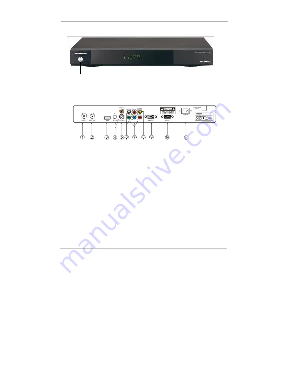
Front panel and rear panel illustration
Front Panel
①
①
POWER
To turn the Stand-by mode ON/OFF.
Rear Panel
①
ANT IN
To connect the antenna here.
②
LOOP OUT
To connect a RF signal from the STB to either the RF Input jack (antenna)
on your VCR or to the antenna input of your TV.
③
HDMI
video output used to connect to your HDMI device.
④
OPTICAL/COAXIAL
Digital audio output.
⑤
S-VIDEO
Y/C output for a S-VHS or Hi-Fi Video Recorder.
⑥
AUDIOL/R
Audio output to connect to your TV.
⑦
YPbPr
High definition video output to connect to your TV.
⑧
VIDEO
CVBS output to connect to your TV.
⑨
VGA
Video output to connect a VGA display monitor.
⑩
RS-232
Serial port for software upgrade.
⑪
POWER
Switch ON/OFF.


