background image

Network Dome Camera

·

Quick Start Guide


20 


8.


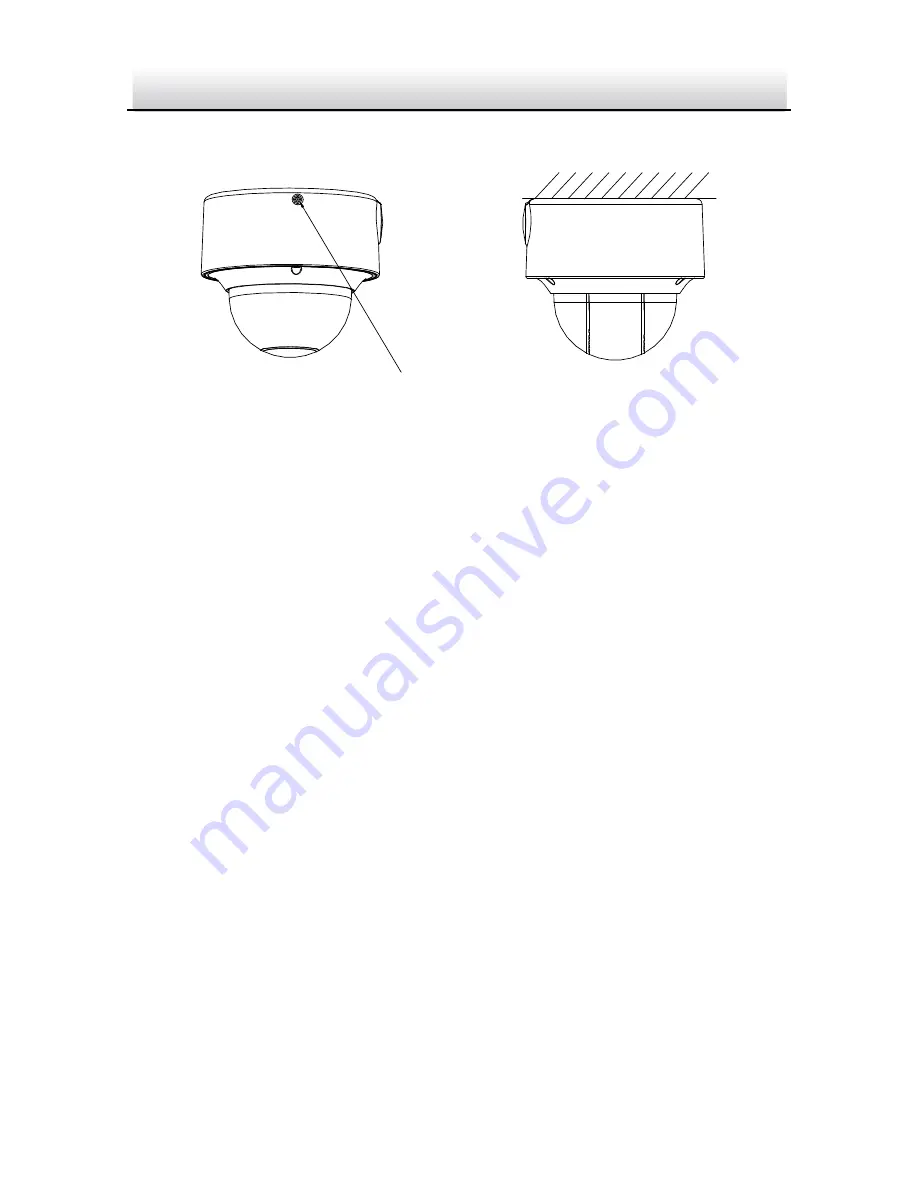
Tighten the lock screw to complete the installation. 

Lock Screw


Figure 2-10


Complete the Installation 

2.2.2


Wall Mounting 

Before you start: 

Wall mounting bracket is not included in package. If you choose this 
mounting type, you have to prepare a bracket first. The wall mounting 
bracket shown below is only for demonstration. 

Note:   

When choosing a wall mounting bracket, you must pay attention to 
the size of the cap which should match the mounting base of the 
camera. 

Summary of Contents for GD-CI-AT3637V

Page 1: ......

Page 2: ...COMPANY SHALL NOT TAKE ANY RESPONSIBILITES FOR ABNORMAL OPERATION PRIVACY LEAKAGE OR OTHER DAMAGES RESULTING FROM CYBER ATTACK HACKER ATTACK VIRUS INSPECTION OR OTHER INTERNET SECURITY RISKS HOWEVER O...

Page 3: ...he instructions may cause harmful interference to radio communications However there is no guarantee that interference will not occur in a particular installation If this equipment does cause harmful...

Page 4: ...in the European Union For proper recycling return this product to your local supplier upon the purchase of equivalent new equipment or dispose of it at designated collection points For more informati...

Page 5: ...ions Injury or equipment damage may occur if any of the cautions are neglected Warnings Proper configuration of all passwords and other security settings is the responsibility of the installer and or...

Page 6: ...smoke odor or noise rise from the device turn off the power at once and unplug the power cable and then please contact the service center Cautions Make sure the power supply voltage is correct before...

Page 7: ...xture Regular part replacement a few parts e g electrolytic capacitor of the equipment shall be replaced regularly according to their average enduring time The average time varies because of differenc...

Page 8: ...g Mounting 16 2 2 2 Wall Mounting 20 2 2 3 Pendant Mouting 23 2 3 Installation of Network Cable Water proof Jacket Optional 26 2 4 Installation of Water proof Tape Optional 28 3 Setting the Network Ca...

Page 9: ...Network Dome Camera Quick Start Guide 8 1 Appearance Description The overview of the dome camera is shown below Overview...

Page 10: ...Network Dome Camera Quick Start Guide 9 1 1 Components 1 2 3 4 5 6 7 8 9 Camera Components 1...

Page 11: ...n No Description 1 Mounting base 2 Dome cover 3 IR 4 Lens 5 Water proof plug 6 Side outlet cover 7 Reset button 8 Serial port 9 Memory card slot 10 GND Note Press RESET about 10s when the camera is po...

Page 12: ...s This camera series has several camera models each of which may have different cable group The following figures and tables show the description of possible cables in this camera series VIDEO 1 2 3 O...

Page 13: ...terminal block interface 4 No 2 alarm input output cable Alarm input IN2 yellow brown GND yellow black Alarm output 2A yellow orange 2B yellow blue 5 No 1 alarm input output cable Alarm input IN1 yel...

Page 14: ...mera that supports IR you are required to pay attention to the following precautions to prevent IR reflection Dust or grease on the dome cover will cause IR reflection Please do not remove the dome co...

Page 15: ...have to disassemble the camera and install the memory card first 2 1 1 Disassembling Steps 1 Loosen the three screws on the edge of the dome cover with the screw driver 2 Lift and put aside the dome...

Page 16: ...Installation Steps 1 Rotate the camera body to completely expose the memory card slot 2 Insert the memory card into the memory card slot and push it to get it mounted Memory Card Install the Memory C...

Page 17: ...where you want to fix the camera 2 Drill the screw holes and the cable hole according to the drill template as the figure below Drill Template Notes The drill template varies according to the differe...

Page 18: ...Outlet 3 Fix the mounting base to the ceiling with the supplied screws Ceiling Mounting Base Screws Install the Mounting Base 4 Align the camera body with the mounting base and rotate the camera body...

Page 19: ...e video output connector to the monitor and connect the power connector to the power supply to adjust the surveillance angle and image 6 Adjust the surveillance angle and image according to the figure...

Page 20: ...a motor driven lens You can adjust the zoom and focus level on PTZ control panel by visiting the camera via web browser or client software Zoom and Focus Adjustment via Web Browser 7 Attach the dome...

Page 21: ...all Mounting Before you start Wall mounting bracket is not included in package If you choose this mounting type you have to prepare a bracket first The wall mounting bracket shown below is only for de...

Page 22: ...amera Quick Start Guide 21 Figure 2 11 Size of the Mounting Base Steps 1 Route the cables install the wall mounting bracket and secure the cap on the bracket Wall Mounting Bracket Cap Install Wall Mou...

Page 23: ...oles of the mounting base with the corresponding screw holes of the cap Cap Mounting Base Install the Mounting Base 3 Secure the mounting base to the cap with screws 4 Align the camera with the mounti...

Page 24: ...the camera and tighten the lock screw to complete the installation Please refer to step 7 and step 8 in section 2 2 1 for more detailed information 2 2 3 Pendant Mouting Before you start Pendant moun...

Page 25: ...amera Quick Start Guide 24 Size of the Mounting Base Steps 1 Route the cables and install the pendant mounting bracket Secure the cap on the bracket Pendant Mounting Bracket Cap Install the Pendant Mo...

Page 26: ...oles of the mounting base with the corresponding screw holes of the cap Cap Mounting Base Install the Mounting Base 3 Secure the mounting base to the cap with screws 4 Align the camera with the mounti...

Page 27: ...me cover back to the camera and tighten the lock screw to complete the installation Please refer to step 7 and step 8 in section 2 2 1 for more detailed information 2 3 Installation of Network Cable W...

Page 28: ...the waterproof endcap in order 2 Crimp an RJ 45 network plug onto the end of the cable taking care to insert the twisted pairs of wires in correct order 3 Place the O type gasket onto the end of the c...

Page 29: ...ter Align the snap and notch i Insert into ii Secure with Figure 2 20 Water proof Accessory Installation 2 4 Installation of Water proof Tape Optional Purpose If the camera is installed outdoor you ca...

Page 30: ...ice the initial length Stretch Stretch Initial Length Waterproof Tape Length After Stretching Figure 2 21 Stretch the Water proof Tape 3 Wrap the water proof tape around the cable connector tightly as...

Page 31: ...ess Press Press Press Figure 2 23 Press the Water proof Tape 5 Wrap the water proof tape around the remaining unused cables tightly as the figure below Figure 2 24 Wrap the Water proof Tape Note Make...

Page 32: ...Network Dome Camera Quick Start Guide 31 Press Press Press Press Figure 2 25 Press the Water proof Tape...

Page 33: ...security risks For avoidance of any network attacks and information leakage please strengthen your own protection If the product does not work properly please contact with your dealer or the nearest s...

Page 34: ...owser as examples to introduce the camera activation Please refer to the User Manual for Activation via Client Software 3 2 1 Activation via Web Browser Steps 1 Power on the camera and connect the cam...

Page 35: ...resetting the password monthly or weekly can better protect your product 4 Confirm the password 5 Click OK to save the password and enter the live view interface 3 2 2 Activation via SADP Software SAD...

Page 36: ...the password STRONG PASSWORD RECOMMENDED We highly recommend you create a strong password of your own choosing using a minimum of 8 characters including upper case letters lower case letters numbers...

Page 37: ...mera in the same subnet with your PC Then install the SADP software or client software to search and change the IP of network camera We will take modifying the IP Address via SADP software as an examp...

Page 38: ...ck Start Guide 37 Figure 3 5 Modify the IP Address 4 Input the password to activate your IP address modification The batch IP address modification is supported by the SADP please refer to the User Man...

Page 39: ...1 Open the web browser 2 In the browser address bar input the IP address of the network camera and press the Enter key to enter the login interface Note The default IP address is 192 168 1 64 If the...

Page 40: ...s to install the plug in Note You may have to close the web browser to finish the installation of the plug in Figure 4 2 Download Plug in 6 Reopen the web browser after the installation of the plug in...

Reviews: