Grundig GCI-K1627D Owner'S Manual Download Page 80

ATW Mode (Auto Tracking White Balance) :
With the Auto Tracking White Balance function, the white balance in a scene will be automatically adjusted while 
temperature colour is changing. The ATW Mode is suitable for environments with a light source having a colour 
temperature in the range roughly from 2450 ~ 10500K.

Indoor/Outdoor Mode :
Select Indoor or Outdoor.

Manual Mode :
In this mode, users can change the White Balance value manually. Users can select a number between 0 ~ 127 in 
the “R-Gain/B-Gain” item to gain the red/blue illuminant on the Live Video Pane. 
Click on < 

 > to con

fi

rm the new setting.

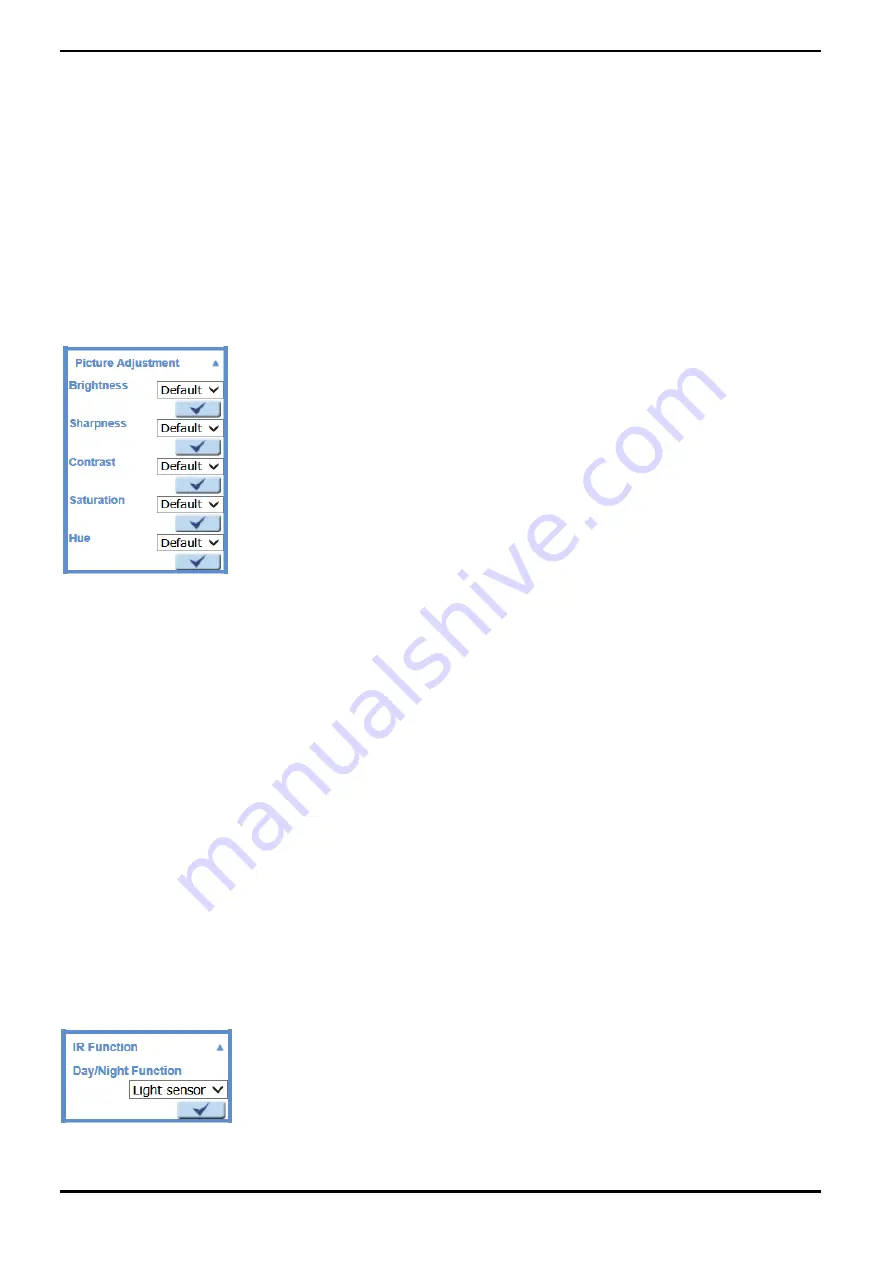
11.3. Picture Adjustment

Display of the Picture Adjustment pull-down menu:

Brightness:
The users can adjust the image’s brightness by adjusting the item. Please select a number from the range of -12 
to +13. To increase the video brightness, select a bigger number. 
Click on < 

 > to con

fi

rm the new setting.

Sharpness:
Increasing the sharpness level can make the image look sharper. Please select a number from the range of +0 to 
+15. This function especially enhances the object’s edges. 
Click on < 

 > to con

fi

rm the new setting.

Contrast:
The camera image contrast level is adjustable. Please choose from a range of -6 to +19. 
Click on < 

 > to con

fi

rm the new setting.

Saturation:
The camera image saturation level is adjustable. Please select from a range of -6 to +19. 
Click on < 

 > to con

fi

rm the new setting.

Hue: 
The camera image hue level is adjustable. Please select from a range of -12 to +13. 
Click on < 

 > to con

fi

rm the new setting.

11.4. IR Function

With the IR cut filter, the Camera can still catch a clear image at night time or in low light conditions.

77

English

Summary of Contents for GCI-K1627D

Page 1: ...GCI K1627D 150 1 29 10 2014 Owner s Manual ASP AG IP Cameras GCI K1627D 2 MP Full HD Indoor Dome IP Camera 3 10 5mm ICR IR 24 LED WDR...

Page 2: ......

Page 3: ...ra 58 10 Recording on Camera 60 11 Schedule 61 12 File Location on PC 61 13 View Information 63 14 Factory Default 64 15 Software Version 65 16 Software Upgrade 65 17 Maintenance 66 10 Streaming Setti...

Page 4: ...ire electric shock or falling objects If any unusual smells or smoke comes out of the unit stop using the product In this case immediately disconnect the power source and contact the service center Co...

Page 5: ...ng the reliability and the life expectancy 4 2 System Requirements To perform the IP Camera via web browser please ensure your PC is in good network connection and meets the system requirements as des...

Page 6: ...r LEDs If the LEDs are unlit please check the LAN connection Green Link Light indicates good network connection Orange Activity Light flashes for network activity indication 4 5 Alarm Application The...

Page 7: ...will pop up Click Unblock to continue Device Search Step 3 Click Find Device again afterwards all IP devices found will be listed on the page as shown in the picture below The IP Camera s default IP...

Page 8: ...d to alter the administrator s password due to security concerns Please refer to section 9 2 Security for further details Additionally users can change the IP Camera s network property either to DHCP...

Page 9: ...ntification Step 2 The Network Setup page will come out Select DHCP and click on the Apply button at the bottom of the page Step 3 Click on OK in the Note of setting the change Wait for one minute to...

Page 10: ...e installation Click on Finish to close the GRUNDIG Viewer window when download is finished For detailed software download procedure please refer to chapter 15 GRUNDIG Viewer Download Procedure NOTE I...

Page 11: ...tting The administrator can set host name system time admin password network related settings etc Further details will be interpreted in chapter 9 System Related Settings Streaming setting The Adminis...

Page 12: ...n granted this privilege by the Administrator Please note that additional equipment will be necessary NOTE This function is only open to the User who has been granted this privilege by the administrat...

Page 13: ...he live video will be displayed as black Click on the restart button to show the live video again Recording Button on off When you click on this button the recordings from the Live View will be saved...

Page 14: ...m tab Each category in the left column will be explained in the following sections NOTE The System configuration page is only accessible by the Administrator 9 1 Host Name System Time Setting Click on...

Page 15: ...ged according to the selected format Sync with Computer Time After selecting this item the video date and time display will be synchronised with the PC Manual The Administrator can set the date time a...

Page 16: ...9 _ Add User Type in the new user name and password and click Add to add the new user The user name can have up to 16 characters the password up to 14 characters The new user will be displayed in the...

Page 17: ...odify the account authority Streaming Authentication Setting The Network Camera provides two types of security settings for an HTTP transaction basic and digest Please choose the one that meets your n...

Page 18: ...ed to install a self signed certificate or a CA signed certificate for implemention of HTTPS After clicking on the HTTPS tab the HTTPS setting page will be shown as in the figure below To use HTTPS on...

Page 19: ...under Create self signed certificate and provide the requested information to install a self signed certificate for the IP Camera Please refer to the last part of this section Provide the Certificate...

Page 20: ...CA Certificate Authority Provide the requested information in the Create Dialog Please refer to the section Provide the Certificate Information for more details When the request is complete the subjec...

Page 21: ...ate is returned install it by uploading the signed certificate Provide the Certificate Information To create a Self signed HTTPS Certificate or a Certificate Request to CA please enter the information...

Page 22: ...ation to which the entity identified in Common Name belongs Organisation Unit Enter the name of the organisational unit to which the entity identified in Common Name belongs Common Name Indicate the n...

Page 23: ...elete IP Address Input the IP address and click the Add button to add a new filtered address The Filtered IP Addresses list box shows the currently configured IP addresses Up to 256 IP address entries...

Page 24: ...bers Then compare their first 30 digits to the binary numbers of 192 168 2 81 a Convert 192 168 2 80 to binary numbers The binary numbers are 11000000 10101000 00000010 01010000 The first 30 digits ar...

Page 25: ...is created by the Certification Authority for the purpose of validating itself Upload the certificate for checking the server s identity Client Certificate Private Key Upload the Client Certificate a...

Page 26: ...several tabs including Basic QoS SNMP and UPnP 9 3 1 Basic Users can choose to connect to the IP Camera through a fixed or dynamic DHCP IP address The IP Camera also provides PPPoE Point to Point Pro...

Page 27: ...lect Use fixed IP address and move the cursor to the IP address blank as indicated below and insert the new IP address e g 192 168 44 230 then go to Default Gateway explained later and type in the app...

Page 28: ...on to be successful For instance when the Administrator changes the HTTP port of the IP Camera which has the IP address 192 168 0 100 from 80 to 8080 the users must type in in the web browser http 192...

Page 29: ...ble routers DSCP Settings The DSCP value range is from 0 to 63 The default DSCP value is 0 which means that DSCP is disabled The IP Camera uses the following QoS Classes Video Audio and Management Vid...

Page 30: ...default value is private SNMP v3 This option contains cryptographic security a higher security level which allows users to set the Authentication password and the Encryption password Enable SNMP v3 Ch...

Page 31: ...r status changes Enable Traps Check the box to activate trap reporting Trap address Enter the IP address of the management server Trap option Warm start A Warm start SNMP trap signifies that the SNMP...

Page 32: ...efer to chapter 17 Install UPnP Components for UPnP component installation procedure Enable UPnP port forwarding When UPnP port forwarding is enabled the IP Camera is allowed to open the web server po...

Page 33: ...domain name so that others can connect to it through this name Enable DDNS Check the item to enable DDNS Provider Select one DDNS host from the provider list Host name Enter the registered domain name...

Page 34: ...e recipients of a message are specified and to whom the message text is transferred The configuration page is shown below Two sets of SMTP can be configured Each set includes the SMTP Server Server Po...

Page 35: ...ails which include server server port user name password and remote folder into the fields Check the box passive mode to be connected to the FTP server by passively receiving the FTP server s IP addre...

Page 36: ...lude the server name for instance http 192 168 1 1 admin php user name and password into the fields Alarm triggered and Motion Detection notifications can then be sent to the specified HTTP server Cli...

Page 37: ...ting page Select By schedule and click Please select to choose the desired schedule from the drop down menu Alarm Type Select an alarm type Normal close or Normal open that corresponds with the alarm...

Page 38: ...m 1 to 20 frames Check the box Continue image upload to upload the triggered images during a certain time or keep uploading until the trigger is off Select Upload for __sec and enter the duration in t...

Page 39: ...red images during a certain time or keep uploading until the trigger is off Select Upload for __sec and enter the duration in the blank The images of the duration will be uploaded by E Mail when the a...

Page 40: ...d As soon as an alarm is triggered the notification will be sent to the specified HTTP server For instance if the custom parameter is set as action 1 group 2 and the HTTP server s name is http 192 168...

Page 41: ...o the blank box e g image jpg The uploaded image s file name format can be set in this section Please select the one that meets your requirements Add date time suffix File name imageYYMMDD_HHNNSS_XX j...

Page 42: ...ion Detection Window displayed on the Live Video Pane shown in the picture below The Motion Detection Window is for defining the motion detection area To change the size of the Motion Detection Window...

Page 43: ...for every 3 pixels by each row and each column please refer to the figure below Detection level 1 100 The default level is 10 This item is to set the detection level for each sampling pixel the small...

Page 44: ...arious parameters as shown in the picture below When a motion is detected event images will be uploaded to the appointed FTP site The Pre trigger buffer recording function allows users to check what h...

Page 45: ...ame to 15 frames NOTE Normally the setting range of the Pre trigger buffer is 1 to 20 However the setting range will change accordingly if the frame rate of MJPEG on the Video Frame Rate setting page...

Page 46: ...able this function by selecting On Users can also activate the function according to the schedule time that is was previously set in the Schedule setting page Select By schedule and click Please selec...

Page 47: ...icro SD SDHC card is activated so that this function can be implemented See section 9 10 Recording on Camera for further details Send Message by FTP The Administrator can select whether to send an ala...

Page 48: ...ard When you check this item the alarm triggered recording will be stored on your Micro SD SDHC card when tampering is detected The pre trigger buffer recording function allows users to check what hap...

Page 49: ...il address and configure various parameters as shown in the figure below When tampering is detected event images will be sent to the appointed e mail address The Pre trigger buffer recording function...

Page 50: ...ame in 9 8 1 Application Alarm Settings Save Click the Save button to save all the Tampering Alarm settings mentioned above 9 8 5 Time lapse In the Time Lapse setting users can set the camera to uploa...

Page 51: ...during a certain time or keep uploading until the trigger is off Select Upload for __sec and enter the duration in the blank The images of the duration will be uploaded to the FTP when the alarm inpu...

Page 52: ...requency as the upload frame rate The setting range is from 1 frame to 15 frames NOTE Normally the setting range of the Pre trigger buffer is 1 to 20 However the setting range will change accordingly...

Page 53: ...e administrator can specify alarm actions that will take place at alarm occurrence All options are listed as follows Triggered Action Multi option The administrator can specify alarm actions that will...

Page 54: ...ded to the FTP when the alarm input is triggered The setting range is from 1 to 9999 seconds Select Upload while trigger is active to keep the images being uploaded to the FTP while the trigger is act...

Page 55: ...0 However the setting range will change accordingly if the frame rate of MJPEG on the Video Frame Rate setting page is 6 or smaller Send HTTP notification Check this item select the destination HTTP a...

Page 56: ...e in the FTP site will be overwritten with a static filename by the new uploaded file Save After completing all the settings mentioned above please click on the Save button to save all the settings in...

Page 57: ...9 10 Recording on Camera for further details Send Message by FTP The Administrator can choose to send an alarm message by FTP when an alarm is detected The Pre trigger buffer recording function allows...

Page 58: ...ion in the blank The images of the duration will be uploaded to the FTP when the alarm input is triggered The setting range is from 1 to 9999 seconds Select Upload while trigger is active to keep the...

Page 59: ...s 6 or smaller Send HTTP notification Check this item select the destination HTTP address and specify the parameters for event notifications when an Alarm is triggered As soon as an alarm is triggered...

Page 60: ...ed to another device with a different software platform NOTE It is not recommended to record with the microSD card for 24 7 continuously as it may not be able to support long term continuous data read...

Page 61: ...the recorded events to the memory card After event recording the device will return to regular recording mode Remove To remove a file select the file first and then click on the Remove button Sort Wh...

Page 62: ...choose Always to allow the Micro SD SDHC Card Recording to be activated all the time Or select a set of schedules from the time frame blank check specific weekdays and set up the start time hour minut...

Page 63: ...me frame to choose the specific weekdays At last type in the start time hour minute and the duration time hour minute for activation of the schedule triggered features The setting range for the durati...

Page 64: ...haracters such as letters and numbers NOTE Users with the Windows 7 or Windows 8 operating system on their PC need to follow the following procedure to be able to use the Snapshot and Web Recording fu...

Page 65: ...on the link to view the system log file The content of this file provides useful information about configuration and connections after system boot up 9 13 2 Parameters Click on this item to view the e...

Page 66: ...button to recall the factory default settings After 30 seconds the system will restart NOTE The IP address will also be restored to default 192 168 1 1 Partial Restore Click on the Partial Restore bu...

Page 67: ...he software version page which is shown in the picture below 9 16 Software Upgrade Software upgrade can be carried out on the Software Upgrade page as shown below NOTE Make sure the upgrade software f...

Page 68: ...upgrade process is finished After the upgrade process is finished the Viewer will return to the Home page Step 4 Close the video browser Step 5 Go to Start on your Windows desktop activate Control Pa...

Page 69: ...w will pop up as shown below Click Save and specify a desired location for saving the configuration file Upload To copy an existing configuration file to the IP Camera please first click on Browse to...

Page 70: ...ric characters and each subtitle can only be 16 characters Users can choose the locations in which the items are to be displayed on the live pane Please note that the items cannot be set to the same l...

Page 71: ...t the GOV length to determine the frame structure I frames and P frames in a video stream for saving bandwidth Longer GOV means decreasing the frequency of I frames The setting range for the GOV lengt...

Page 72: ...setting of H 264 1 is 4096 kbps and of H 264 2 H 264 3 H 264 4 is 1024 kbps The setting range for H 264 1 is from 64 to 2048 kbps and for H 264 2 H 264 3 H 264 4 it is from 64 to 2048 kbps Click Save...

Page 73: ...64 triple stream is selected under Video Resolution in the Video Format Setting Enable the H 264 3 ROI Setting When you check the box the H 264 3 ROI Window will be displayed To change the size of the...

Page 74: ...o OCX Protocol In the Video OCX protocol setting page users can select RTP over UDP RTP over TCP RTSP over HTTP or MJPEG over HTTP for streaming media over the network In the case of multicast network...

Page 75: ...y available when a video format with 50 fps is selected under TV System The setting range is 1 to 25 or 1 to 50 For NTSC the default setting can be 30 fps or 60 fps 60 fps is only available when a vid...

Page 76: ...mask s size and drag and drop the frame to place it on the target zone NOTE It is suggested to set the Video Mask twice as big as the object How to cancel a mask If you uncheck the checkbox of the Vid...

Page 77: ...de the local remote site can only talk to the other site Simplex Listen only In the Listen only Simplex mode the local remote site can only listen to the other site Disable Select this item to turn th...

Page 78: ...iguration page Details of each parameter setting are described in the following sub sections 11 1 Exposure Setting Display of the Exposure pull down menu The exposure is the amount of light received b...

Page 79: ...perature the camera will calculate the correct values for all colours The camera can perform a measurement by itself or the user can set up the reference colour temperature manually The scale unit of...

Page 80: ...brightness by adjusting the item Please select a number from the range of 12 to 13 To increase the video brightness select a bigger number Click on to confirm the new setting Sharpness Increasing the...

Page 81: ...he monochrome night mode stability in ascenario where IR illumination is dominant In this mode when the external IR illuminator is turned on the IR cut filter of the IP Camera will stay open i e monoc...

Page 82: ...atively enhanced noise reduction Click on to confirm the new setting 11 5 4 DIS The DIS function can minimise blurry images caused by minor camera shake The default setting is On Click on to confirm t...

Page 83: ...e Mode Day this profile will be loaded when IR cut is off Night this profile will be loaded when IR cut is on Time indicates the start time and time duration for the schedule Camera Profile Setup Step...

Page 84: ...e gaps between schedules the camera will apply the setting of the last profile 11 7 TV System Setup Select a video format according to the user s TV system PAL NTSC The default setting is WDR autoiris...

Page 85: ...eo format with WDR autoiris to activate both the WDR and the Auto Iris functions 12 Logout When you press the Logout tab at the top of the page the login window will pop up This permits login with ano...

Page 86: ...monitor multiple IP Cameras and Video Servers and allows the user to monitor simultaneously 16 sites per group up to 10 groups within several clicks For further information on the CMS software please...

Page 87: ...n the Security tab and select Internet Step 4 Down the page click on Default level and then click OK to confirm the setting Close the browser window and open a new one later when accessing the IP Came...

Page 88: ...gs Step 1 3 Please refer to the previous section above Step 4 Down the page click on Custom level see the picture below to change ActiveX controls and plug in settings The Security Settings screen is...

Page 89: ...6 Download signed ActiveX controls 7 Download unsigned ActiveX controls 8 Initialize and script ActiveX controls not marked as safe for scripting 9 Run ActiveX controls and plug ins 10 Script ActiveX...

Page 90: ...Step 2 Setup starts Please wait for a while until the loading bar runs out Step 3 Click on Finish to close the GRUNDIG Viewer installation page 87 English...

Page 91: ...epending on the camera model 16 Install UPnP Components Please follow the instructions below to install UPnP components The procedure is for Windows XP for other systems please refer to the correspond...

Page 92: ...lick on Add Remove Windows Components in the Add or Remove Programs page Step 3 Select Networking Services from the Components list in the Windows Components Wizard window and then click on Details 89...

Page 93: ...ct UPnP User Interface in the Networking Services subcomponents list and then click on OK Step 5 Click on Next in the Windows Components Wizard page Step 6 Click on Finish to complete the installation...

Page 94: ...d or Remove Programs In the Currently installed programs list select GRUNDIG Viewer and click the button Remove to uninstall the existing GRUNDIG Viewer as shown in the figure below Deleting Temporary...

Page 95: ...STEP 2 Click on Delete in the first pop up window Then tap Delete Files in the Temporary Internet files section in the next pop up window 92 English...

Page 96: ...ering Alarm On Off Time Lapse Off On 60 3600s Manual Trigger On Off Schedule Daily Weekly Start Time and Duration Alarm Event Alarm Input Motion Detection or Schedule Image Transfer or Alarm Message b...

Page 97: ...P ARP Firmware Upgrade by Web Browser or Grundig finder from ver 1 17 Configuration Over Remote PC Multi Language Webpage English German French Italian Russian Turkish LED Indicator Power link active...

Page 98: ...Measurement Procedure EMI AS NZS CISPR 22 2009 EN55022 CLASS A 2010 EN61000 3 2 2006 A1 2009 A2 2009 EN61000 3 3 2008 Measurement Procedure EMS AS NZS CISPR 24 2009 EN 50130 4 1995 A1 1998 A2 2003 IE...

Reviews: