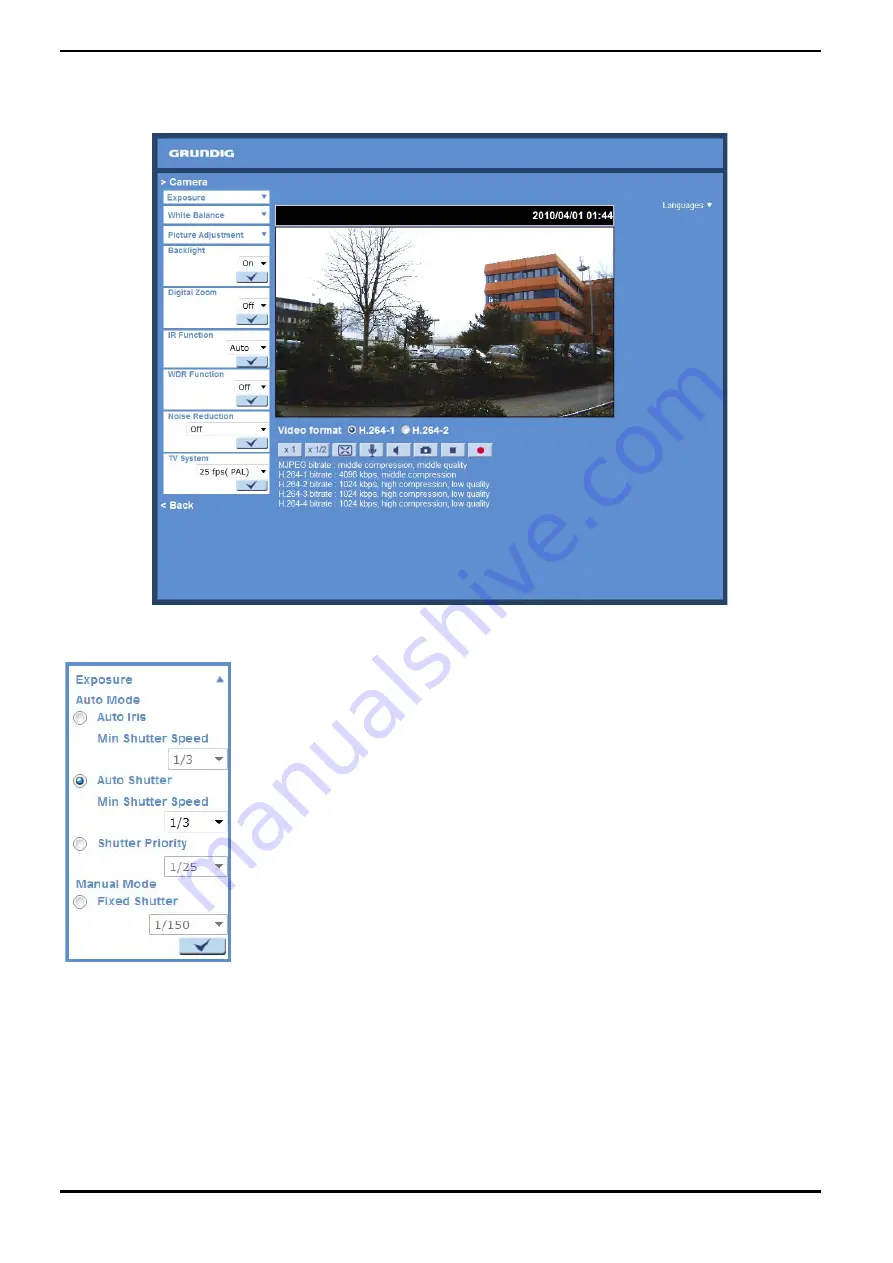
Grundig GCI-K1526T Owner'S Manual Download Page 70

11. Camera Settings

The picture below is the camera configuration page. Details of each parameter setting are described in the 
following subsections.

11.1. Exposure Setting

Display of the Exposure pull-down menu:

The exposure is the amount of light received by the image sensor and is determined by the width of lens 
diaphragm opening, the amount of exposure by the sensor (shutter speed) and other exposure parameters. With 
this item, users can define how the Auto Exposure function works.

Auto Mode :
- Auto Iris Mode: 
In this mode, the exposure gives priority to the auto iris. The minimum shutter speed can be set from 1/1.5 to 1/25 
sec. AGC (Auto Gain Control) will function automatically according to the light conditions of the subject.

68

English

Summary of Contents for GCI-K1526T

Page 1: ...GCI K1526T 60 1 10 05 2012 Owner s Manual ASP AG IP Cameras Domes GCI K1526T 2 Megapixel Full HD CMOS Bullet IP Camera ICR IR 23 LED...

Page 2: ......

Page 3: ...18 View Parameters 57 19 Factory Default 57 20 Software Version 58 21 Software Upgrade 59 22 Maintenance 60 10 Streaming Settings 61 1 Video Format 61 2 Video Compression 63 3 Video OCX Protocol 64 4...

Page 4: ...h a condition may cause fire or electric shock If this product fails to operate normally contact the nearest service center Never disassemble or modify this product in any way GRUNDIG is not liable fo...

Page 5: ...for quick wiring Definition for each connector will be given as follows SD Card Slot Reset Button Follow the steps below to reach the SD Card Slot Reboot Button and Factory Default Button on the IP Ca...

Page 6: ...Step 2 Unscrew the screw on the Camera Housing and remove the Front Housing SD Card Slot Factory Default Button Reboot Button 4 English...

Page 7: ...Cable Connection Use of Category 5 Ethernet cable is recommended for network connection to have best transmission quality cable length shall not exceed 100 meters Connect one end of the Ethernet cable...

Page 8: ...plied Inner Hex Wrench to loosen the hex bolt on the side of the Bracket Mount to adjust the position of the IP Camera 5 Accessing the Camera For initial access to the IP Camera users can search the c...

Page 9: ...Step 3 Click Find Device again afterwards all IP devices found will be listed on the page as shown in the picture below The IP Camera s default IP address is 192 168 1 1 Step 4 Double click or right...

Page 10: ...ork property either to DHCP or Static IP directly in the device finding list Please refer to the following section for changing the IP Camera s network property Example of changing the network propert...

Page 11: ...After double clicking on the IP Camera the login window will appear Step 5 Enter User name and Password to access the IP Camera Installing the GRUNDIG Viewer Software Online For initial access to the...

Page 12: ...Home Page cannot be shown to the users who have installed the GRUNDIG Viewer on the PC previously please refer to the procedure in chapter 17 Delete the Existing GRUNDIG Viewer Once logged in to the I...

Page 13: ...t page of the user friendly browser based configuration interface The page Video Format can be found in the IP camera menu under the path Streaming Video Format Under the Video Resolution section in t...

Page 14: ...12 English...

Page 15: ...For more streaming combinations with several streams please refer to Streaming Video Format in the camera menu 13 English...

Page 16: ...ng setting The Administrator can configure a specific video resolution video compression mode video protocol audio transmission mode etc in this page Further details will be interpreted in chapter 10...

Page 17: ...on off Click on the Speaker button to mute activate the audio Snapshot button After clicking this button the JPEG snapshots will be automatically saved in the appointed place The default place of savi...

Page 18: ...he default storage location for the recordings is C See section 9 14 File Location on PC for further details NOTE Users with the Windows 7 operating system on their PC who want to use the Recording fu...

Page 19: ...m tab Each category in the left column will be explained in the following sections NOTE The System configuration page is only accessible by the Administrator 9 1 Host Name System Time Setting Click on...

Page 20: ...display will be synchronised with the PC Manual The Administrator can set the date time and day manually Entry format should be identical with the format shown next to the enter fields Sync with NTP...

Page 21: ...es Camera control Talk and Listen can be assigned I O access This item supports fundamental functions that enable users to view the video when accessing the camera Camera control This item allows the...

Page 22: ...to install a self signed certificate or a CA signed certificate for implemention of HTTPS After clicking on the HTTPS tab the HTTPS setting page will be shown as in the figure below To use HTTPS on t...

Page 23: ...under Create self signed certificate and provide the requested information to install a self signed certificate for the IP Camera Please refer to the last part of this section Provide the Certificate...

Page 24: ...CA Certificate Authority Provide the requested information in the Create Dialog Please refer to the section Provide the Certificate Information for more details When the request is complete the subjec...

Page 25: ...ate is returned install it by uploading the signed certificate Provide the Certificate Information To create a Self signed HTTPS Certificate or a Certificate Request to CA please enter the information...

Page 26: ...ation to which the entity identified in Common Name belongs Organisation Unit Enter the name of the organisational unit to which the entity identified in Common Name belongs Common Name Indicate the n...

Page 27: ...listed IP addresses IPv4 Select Allow or Deny from the drop down list and click the Apply button to determine the IP Filter behaviour Add Delete IP Address Input the IP address and click the Add butto...

Page 28: ...se of validating itself Upload the certificate for checking the server s identity Client Certificate Private Key Upload the Client Certificate and Private Key for authenticating the IP Camera itself S...

Page 29: ...ith several tabs including Basic QoS SNMP and UPnP Basic Users can choose to connect to the IP Camera through a fixed or dynamic DHCP IP address The IP Camera also provides PPPoE Point to Point Protoc...

Page 30: ...P address blank as indicated below and insert the new IP address e g 192 168 44 230 then go to Default Gateway explained later and type in the appropriate setting e g 192 168 44 1 Click on Save to con...

Page 31: ...4 to 65535 MJPEG over HTTP port The default setting of the MJPEG over HTTP Port is 8008 the setting range is from 1024 to 65535 HTTPS port The default setting of the HTTPS Port is 443 the setting rang...

Page 32: ...e setting NOTE To enable this function please make sure the switches routers in the network support QoS SNMP Simple Network Management Protocol With Simple Network Management Protocol SNMP support the...

Page 33: ...activate trap reporting Trap address Enter the IP address of the management server Trap community Enter the community to use when sending a trap message to the management system Trap option Warm star...

Page 34: ...UPnP component is installed on your computer Please refer to chapter 16 Install UPnP Components for UPnP component installation procedure Enable UPnP port forwarding When UPnP port forwarding is enabl...

Page 35: ...domain name so that others can connect to it through this name Enable DDNS Check the item to enable DDNS Provider Select one DDNS host from the provider list Host name Enter the registered domain name...

Page 36: ...e text based protocol where one or more recipients of a message are specified and to whom the message text is transferred The configuration page is shown below Two sets of SMTP can be configured Each...

Page 37: ...rotocol FTP site when motion is detected Users can assign an alarm message to up to two FTP sites The FTP setting page is shown below Enter the FTP details which include server server port user name p...

Page 38: ...nclude the server name for instance http 192 168 1 1 admin php user name and password into the fields Alarm triggered and Motion Detection notifications can then be sent to the specified HTTP server C...

Page 39: ...corresponds with the alarm application Alarm Output Define the alarm output signal as high or low for the normal alarm output status according to the current alarm application Triggered Action Multi o...

Page 40: ...iggered The post trigger buffer time range is from 1 to 20 frames Check the box Continue image upload to upload the triggered images during a certain time or keep uploading until the trigger is off Se...

Page 41: ...igger buffer time range is from 1 to 20 frames Check the box Continue image upload to upload the triggered images during a certain time or keep uploading until the trigger is off Select Upload for __s...

Page 42: ...d As soon as an alarm is triggered the notification will be sent to the specified HTTP server For instance if the custom parameter is set as action 1 group 2 and the HTTP server s name is http 192 168...

Page 43: ...o the blank box e g image jpg The uploaded image s file name format can be set in this section Please select the one that meets your requirements Add date time suffix File name imageYYMMDD_HHNNSS_XX j...

Page 44: ...Window is for defining the motion detection area To change the size of the Motion Detection Window move the mouse cursor to the edge of the frame and draw it outward inward When you move the mouse cur...

Page 45: ...level is 10 This item is to set the detection level for each sampling pixel the smaller the value the more sensitive the detection is Sensitivity level 1 100 The default level is 80 which means if 20...

Page 46: ...ted Upload Image by FTP After selecting this item the Administrator can assign a FTP site and configure various parameters as shown in the picture below When a motion is detected event images will be...

Page 47: ...trigger is active to keep the images being uploaded to the FTP while the trigger is active i e until the alarm is stopped Set the Image frequency as the upload frame rate The setting range is from 1...

Page 48: ...ollows Enable Alarm Output Check this item and select the predefined type of alarm output to enable alarm relay output when network failure is detected Record Stream to SD Card When you check this ite...

Page 49: ...detected Send Alarm Message by E Mail The Administrator can choose to send an alarm message by E Mail when Network Failure is detected 9 11 Tampering The Tampering Alarm function helps the IP Camera...

Page 50: ...e trigger is turned off NOTE Please make sure that the local recording with Micro SD SDHC card is activated so that this function can be implemented See section 9 13 Recording on Camera for further de...

Page 51: ...ames NOTE Make sure SMTP or FTP configuration has been completed See section 9 5 Mail and 9 6 FTP for further details Send HTTP notification Check this item select the destination HTTP address and spe...

Page 52: ...formation section in the Storage Management page Device Setting Click on the Format button to format the memory card Disk Cleanup Setting Users can enable an automatic recordings cleanup by checking t...

Page 53: ...n the Remove button Sort When you click on the Sort button the files in the Recording list will be listed in name and date order NOTE The capital letters A M or R appearing in the very beginning of a...

Page 54: ...ypes of schedule mode are offered Always and Only during time frame You can set up the time frame according to your requirements or you can choose Always to allow the Micro SD SDHC Card Recording to b...

Page 55: ...contains valid characters such as letters and numbers NOTE Users with the Windows 7 operating system on their PC need to follow the following procedure to be able to use the Snapshot function First yo...

Page 56: ...s adjustment please refer to the iris adjustment procedure in the sub menu Iris Adjustment to adjust the iris 9 16 View Log File Click on the link to view the system log file The content of this file...

Page 57: ...nd their privileges see section 9 2 Security View User Login Information All the users in the network will be listed in the User Information zone as shown below The picture below shows User 4321 This...

Page 58: ...e the Administrator will be able to view each user s privileges As the picture above shows User 1 1 0 1 1 1 0 1 I O access Camera control Talk Listen see 9 2 Security This denotes that the user has be...

Page 59: ...k on this item to view the entire system s parameter setting 9 19 Factory Default The factory default setting page is shown below Follow the instructions to reset the IP Camera to factory default sett...

Page 60: ...estart NOTE The IP address will also be restored to default 192 168 1 1 Reboot When you click on the Reboot button the system will restart without changing the current settings 9 20 Software Version T...

Page 61: ...land Step 3 Click on Upgrade The system will first check whether the upgrade file exists or not and then begin to upload the upgrade file Subsequently the upgrade status bar will be displayed on the p...

Page 62: ...the configuration file bin to a specified location for future use When you click on the Export button the File Download window will pop up as shown below Click Save and specify a desired location for...

Page 63: ...items to display data date time text on the live video pane The maximum length of the string is 18 alphanumeric characters Click Save to confirm the Text Overlay setting Video Rotation Type Users can...

Page 64: ...go back to Normal View 180 degree rotation Selecting the 180 Degree rotation will inverse the image 180 counter clockwise Click Save to confirm the setting GOV Settings Users can set the GOV length to...

Page 65: ...setting of H 264 1 is 4096 kdps and of H 264 2 H 264 3 H 264 4 is 1024 kbps The setting range for H 264 1 is from 64 to 8192 kbps and for H 264 2 H 264 3 H 264 4 it is from 64 to 2048 kbps Click Save...

Page 66: ...n select the Multicast mode The Video OCX Protocol page is as follows Video OCX protocol setting options include RTP over UDP RTP over RTSP TCP RTSP over HTTP MJPEG over HTTP Select a mode according t...

Page 67: ...g page is shown below MJPEG H 264 1 H 264 2 H 264 3 H 264 4 Frame Rate The default setting of MJPEG H 264 1 H 264 2 H 264 3 H 264 4 Frame Rate is 25 fps The setting range is from 1 to 25 Click on Save...

Page 68: ...and drag and drop the frame to place it on the target zone NOTE It is suggested to set the Video Mask twice as big as the object Cancel a mask If you uncheck the checkbox of the Video Mask that is me...

Page 69: ...de the local remote site can only talk to the other site Simplex Listen only In the Listen only Simplex mode the local remote site can only listen to the other site Disable Select this item to turn th...

Page 70: ...sensor and is determined by the width of lens diaphragm opening the amount of exposure by the sensor shutter speed and other exposure parameters With this item users can define how the Auto Exposure f...

Page 71: ...itself or the user can set up the reference colour temperature manually The scale unit of the colour temperature is Kelvin K The following list shows the colour temperature of some light sources for r...

Page 72: ...ra image contrast level is adjustable Please choose from a range of 6 to 19 Click on to confirm the new setting Saturation The camera image saturation level is adjustable Please select from a range of...

Page 73: ...r of the IP Camera will stay open i e monochrome night mode preventing the camera from returning to colour day mode when the IR illumination is dominant Additionally the day night IR switching mechani...

Page 74: ...in various conditions The Noise Reduction function is configurable with the following options 3DNR Low 3DNR Mid 3DNR Hi SPQ SPQ 3DNR Low SPQ 3DNR Mid SPQ 3DNR Hi Click on to confirm the new setting 11...

Page 75: ...monitor multiple IP Cameras and Video Servers and allows the user to monitor simultaneously 16 sites per group up to 10 groups within several clicks For further information on the CMS software please...

Page 76: ...n the Security tab and select Internet Step 4 Down the page click on Default level and then click OK to confirm the setting Close the browser window and open a new one later when accessing the IP Came...

Page 77: ...gs Step 1 3 Please refer to the previous section above Step 4 Down the page click on Custom level see the picture below to change ActiveX controls and plug in settings The Security Settings screen is...

Page 78: ...6 Download signed ActiveX controls 7 Download unsigned ActiveX controls 8 Initialize and script ActiveX controls not marked as safe for scripting 9 Run ActiveX controls and plug ins 10 Script ActiveX...

Page 79: ...Step 2 Setup starts Please wait for a while until the loading bar runs out Step 3 Click on Finish to close the GRUNDIG Viewer installation page 77 English...

Page 80: ...epending on the camera model 16 Install UPnP Components Please follow the instructions below to install UPnP components The procedure is for Windows XP for other systems please refer to the correspond...

Page 81: ...lick on Add Remove Windows Components in the Add or Remove Programs page Step 3 Select Networking Services from the Components list in the Windows Components Wizard window and then click on Details 79...

Page 82: ...ct UPnP User Interface in the Networking Services subcomponents list and then click on OK Step 5 Click on Next in the Windows Components Wizard page Step 6 Click on Finish to complete the installation...

Page 83: ...d or Remove Programs In the Currently installed programs list select GRUNDIG Viewer and click the button Remove to uninstall the existing GRUNDIG Viewer as shown in the figure below Deleting Temporary...

Page 84: ...STEP 2 Click on Delete in the first pop up window Then tap Delete Files in the Temporary Internet files section in the next pop up window 82 English...

Page 85: ...g Simultaneous H 264 1080p 25fps MJPEG D1 25fps H 264 1080p 25fps H 264 4CIF 25fps Network Protocol IPv4 v6 TCP IP UDP RTP RTSP HTTP HTTPS DHCP PPPoE UPnP SMTP ICMP IGMP SNMP IEEE802 1x QoS ONVIF SD m...

Page 86: ...84 English...

Page 87: ...pplied harmonised standards and technical specifications EN 55022 CLASS A 2006 A1 2007 Class A EN 61000 3 2 2006 A1 2009 EN 61000 3 3 2008 AS NZS CISPR 22 2009 Class A EN 50130 4 1995 A1 1998 A2 2003...

Reviews: