background image

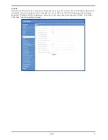
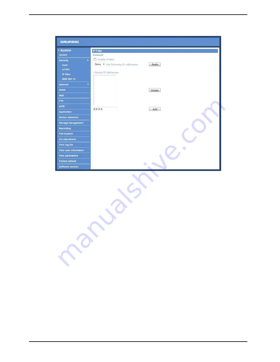
<IP Filter> :

When using the IP filter, access to the IP Camera can be restricted by denying/allowing specific IP addresses.

General :
- Enable IP Filter:
Check the box to enable the IP Filter function. Once enabled, the listed IP addresses (IPv4) will be allowed/denied 
access to the IP Camera.

Select “Allow” or “Deny” from the drop-down list and click the <Apply> button to determine the IP Filter 
behaviour.

- Add/Delete IP Address:
Input the IP address and click the <Add> button to add a new filtered address.

The Filtered IP Addresses list box shows the currently configured IP addresses. Up to 256 IP address entries may 
be specified. 

To remove an IP address from the list, please select the IP and then click the <Delete> button.

24

English

Summary of Contents for GCI-H0522V

Page 1: ...GCI K0512W 14 1 01 02 2011 Owner s Manual ASP AG IP Cameras Domes GCI K0512W 1080P Full HD Flat Fixed Dome IP Camera ...

Page 2: ......

Page 3: ...ng 62 5 Contrast Setting 62 6 Saturation Setting 62 7 Hue Setting 62 8 TV System Setup 62 12 Logout 63 13 CMS Software Introduction 64 14 Internet Security Settings 64 15 GRUNDIG Viewer Download Procedure 67 16 Install UPnP Components 69 1 Introduction Following the high standards of GRUNDIG IP Cameras this IP Camera is capable of serving real time streaming and makes the images run smoothly 25 im...

Page 4: ...f this product fails to operate normally contact the nearest service center Never disassemble or modify this product in any way GRUNDIG is not liable for problems caused by unauthorized modifications or attempted repair To prevent fire or electric shock do not expose the inside of this device to rain or moisture 3 Package Contents These parts are included 4 Installation Do not install in a locatio...

Page 5: ...ements as described below Personal Computer 1 Intel Pentium M 2 16 GHz or Intel Core 2 Duo 2 0 GHz 2 2 GB RAM or more Operating System Windows XP Windows VISTA Windows 7 Web Browser Microsoft Internet Explorer 6 0 or later Firefox Chrome Safari Network Card 10Base T 10 Mbps or 100Base TX 100 Mbps operation Viewer ActiveX control plug in for Microsoft IE 3 English ...

Page 6: ...Connection For waterproofing the RJ 45 Dongle please us a corresponding Screw On Plug not included in the package Please refer to the instructions for the Screw on Plug to waterproof the connection correctly English ...

Page 7: ...dd or Remove Programs In the Currently installed programs list select GRUNDIG Viewer and click the button Remove to uninstall the existing GRUNDIG Viewer as shown in the figure below Deleting Temporary Internet Files To improve the browser performance it is suggested to clean up all the files in the Temporary Internet Files The procedure is as follows for other web browsers please read the corresp...

Page 8: ...sing the Camera For initial access to the IP Camera users can search the camera through the installer program GRUNDIG Finder exe which can be found on the supplied CD GRUNDIG Finder Software Setup Step 1 Double click on the program GRUNDIG Finder exe see the icon below its window will appear as shown below Then click the Find Device button 6 English ...

Page 9: ...ow will pop up Click Unblock to continue Device Search Step 3 Click Find Device again and all the IP devices found will be listed on the page as shown in the picture below The IP Camera s default IP address is 192 168 1 1 7 English ...

Page 10: ...s strongly advised that administrator s password be altered for security concerns Refer to section 9 2 Security for further details Additionally users can change the IP Camera s network property either DHCP or Static IP directly in the device finding list Refer to the following section for changing the IP Camera s network property Example of changing IP Camera s network property Users can directly...

Page 11: ... Step 2 The Network Setup page will come out Select DHCP and press the Apply button down the page Step 3 Click OK on the Note of setting change Wait for one minute to re search the IP Camera Step 4 Click the Find Device button to search all the devices Then select the IP Camera with the correct MAC address Double click on the IP Camera and the login window will come out Step 5 Enter User name and ...

Page 12: ...ee the picture below Right click on the Information Bar and select Install ActiveX Control to allow the installation Then the security warning window will pop up Click Install to carry on software installation Click Finish to close the GRUNDIG Viewer window when download is finished For the detailed software download procedure please refer to chapter 10 GRUNDIG Viewer Download Procedure Once logge...

Page 13: ...ng to the IP Camera Adjust zoom and focus as necessary to produce a clear image Step 1 Unscrew the IP Dome Camera s cover Step 2 Loosen the tilt fixed screw and adjust the camera s tilt angle loosen the focus fixed screw and rotate the lens counter clockwise to adjust the focus 11 English ...

Page 14: ...ive video of the targeted area System setting The administrator can set host name system time admin password network related settings etc Further details will be interpreted in chapter 9 System Related Settings Camera setting Users can adjust various camera parameters Logout Click on the tab to re login the IP Camera with another username and password Languages Please choose one of the supported l...

Page 15: ...to the remote site Click on the button to switch it to on off Please refer to section 9 2 Security User Add user Talk Listen for further details This function is only open to the User who has been granted this privilege by the Administrator Please note that additional equipment will be necessary NOTE This Flat Fixed Dome IP Camera does not have the Talk function Speaker button on off Press the Spe...

Page 16: ...ress the stop button to disable video streaming the live video will be displayed as black Press the restart button to show the live video again Recording button on off Press the button and the recordings from the Live View will be saved to the location specified in the File Location snapshot page The default storage location for the recording is C See section 9 12 File Location for further details...

Page 17: ...tem tab Each category in the left column will be explained in the following sections NOTE The System configuration page is only accessible by the Administrator 9 1 Host Name System Time Setting Press the first category System in the left column the page is shown below 15 English ...

Page 18: ... time display will synchronise with the PC s Manual The Administrator can set date time and day manually Entry format should be identical with that shown next to the enter fields Sync with NTP server Network Time Protocol NTP is an alternate way to synchronise your camera s clock with a NTP server Please specify the server you wish to synchronise in the enter field Then select an update interval f...

Page 19: ... a z 0 9 _ Add User Type the new user s name and password and click Add to add the new user The user name can have up to 16 characters the password up to 14 characters The new user will be displayed in the user name list A maximum of 20 user accounts can be set To each user the privileges of Camera control Talk and Listen can be assigned I O access This item supports fundamental functions that ena...

Page 20: ...n click Delete to remove it To edit a user pull down the user list and select a user name Click Edit to edit the user s password and privilege NOTE It is required to enter the User password and to select the function open to the user When finished click Save to modify the account authority 18 English ...

Page 21: ...uired to install a self signed certificate or a CA signed certificate for implementing HTTPS Click the HTTPS tab and the HTTPS setting page is shown as the figure below To use HTTPS on the IP Camera a HTTPS certificate must be installed The HTTPS certificate can be obtained by either creating and sending a certificate request to a Certificate Authority CA or creating a self signed HTTPS certificat...

Page 22: ... under Create self signed certificate and provide the requested information to install a self signed certificate for the IP Camera Please refer to the last part of this section Provide the Certificate Information for more details NOTE The self signed certificate does not provide the same high level of security as when using a CA issued certificate 20 English ...

Page 23: ...e from CA Provide the requested information in the Create Dialog Please refer to the following Provide the Certificate Information for more details When the request is complete the subject of the Created Request will be shown in the field Click Properties below the Subject field copy the PEM formatted request and send it to your selected CA 21 English ...

Page 24: ...cate is returned install it by uploading the signed certificate Provide the Certificate Information To create a Self signed HTTPS Certificate or a Certificate Request to CA please enter the information as requested 22 English ...

Page 25: ...sation to which the entity identified in Common Name belongs Organisation Unit Enter the name of the organisational unit to which the entity identified in Common Name belongs Common Name Indicate the name of the person or other entity that the certificate identifies often used to identify the website Valid days Self signed Certificate Only Enter the period in days 1 9999 to indicate the valid peri...

Page 26: ...access to the IP Camera Select Allow or Deny from the drop down list and click the Apply button to determine the IP Filter behaviour Add Delete IP Address Input the IP address and click the Add button to add a new filtered address The Filtered IP Addresses list box shows the currently configured IP addresses Up to 256 IP address entries may be specified To remove an IP address from the list please...

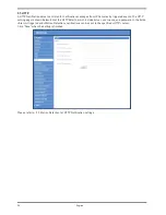
Page 27: ...urpose of validating itself Upload the certificate for checking the server s identity Client Certificate Private Key Upload the Client Certificate and Private Key for authenticating the IP Camera itself Settings Identity Enter the user identity associated with the certificate Up to 16 characters can be used Private Key Password Enter the password maximum 16 characters for your user identity Enable...

Page 28: ...th tabs including Basic QoS SNMP and UPnP Basic Users can choose to connect to the IP Camera through a fixed or dynamic DHCP IP address The IP Camera also provides PPPoE Point to Point Protocol over Ethernet support for users who connect to the network via PPPoE 26 English ...

Page 29: ...ndicated below and insert the new IP address e g 192 168 7 123 then go to the Default Gateway explained later and type in the appropriate setting e g 192 168 7 254 Press Save to confirm the new setting When using a static IP address to login to the IP Camera users can access it either through the GRUNDIG Finder software see 6 Accessing the Camera or input the IP address in the URL bar and press En...

Page 30: ...92 168 0 100 from 80 to 8080 the users must type in the web browser http 192 168 0 100 8080 instead of http 192 168 0 100 RTSP port The default setting of RTSP Port is 554 the setting range is from 1024 to 65535 MJPEG over HTTP port The default setting of MJPEG over HTTP Port is 8008 the setting range is from 1024 to 65535 HTTPS port The default setting of HTTPS Port is 443 the setting range is fr...

Page 31: ...t from DiffServ capable routers DSCP Settings The DSCP value range is from 0 to 63 The default DSCP value is 0 which means DSCP is disabled The IP Camera uses the following QoS Classes Video Audio and Management Video This class consists of applications such as MJPEG over HTTP RTP RTSP and RTSP HTTP Audio This setting is only available for the IP Cameras which support audio Management This class c...

Page 32: ...ich has read write access to all supported SNMP objects except read only objects The default value is private Traps for SNMP v1 v2 Traps are used by the IP Camera to send messages to a management system about important events or status changes Enable Traps Check the box to activate trap reporting Trap address Enter the IP address of the management server Trap community Enter the community to use w...

Page 33: ... icon of the connected IP Cameras will appear in My Network Places to allow for direct access as shown below NOTE To enable this function please make sure the UPnP component is installed on your computer Please refer to chapter 16 Install UPnP Components for UPnP component installation procedure 31 English ...

Page 34: ...st name to be constantly synchronised with a dynamic IP address In other words it allows those using a dynamic IP address to be associated to a static domain name so that others can connect to it through this name Enable DDNS Check the item to enable DDNS Provider Select one DDNS host from the provider list Host name Enter the registered domain name in the field Username E mail Enter the username ...

Page 35: ...ed protocol where one or more recipients of a message are specified and to whom the message text is transferred The configuration page is shown below Two sets of SMTP can be configured Each set includes SMTP Server Account Name Password and E mail Address settings Concerning the SMTP server contact your network service provider for more specific information Click the Save button to save the change...

Page 36: ...rotocol FTP site when motion is detected Users can assign an alarm message to up to two FTP sites The FTP setting page is shown below Enter the FTP details which include server server port user name password and remote folder in the fields Click Save when the setting is finished 34 English ...

Page 37: ...setting page is shown below Enter the HTTP details which include server user name and password in the fields Alarm triggered and Motion Detection notifications can be sent to the specified HTTP server Click Save when the setting is finished Please refer to 9 9 Motion Detection for HTTP Notification settings 35 English ...

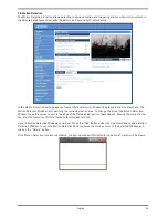
Page 38: ... area To change the size of the Motion Detection Window move the mouse cursor to the edge of the frame and draw it outward inward Moving the mouse to the center of the frame can shift the frame to the intended location Up to 10 Motion Detection Windows can be set Press the Add button under the Live View Pane to add a Motion Detection Window To cancel a Motion Detection Window move the mouse cursor...

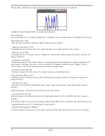
Page 39: ...ve it is Meanwhile when the value is bigger the red horizontal line in the motion indication window will be accordingly lower Time interval sec 0 7200 The default interval is 10 This value is the interval between each detected motion Triggered Action Multi option The Administrator can specify alarm actions that will take place when the alarm is triggered All options are listed as follows Enable Al...

Page 40: ... be sent to the appointed e mail address NOTE Make sure SMTP or FTP configuration has been completed See section 9 5 Mail and 9 6 FTP for further details Send HTTP notification Check this item select the destination HTTP address and specify the parameters for event notifications when Motion Detection is triggered When an alarm is triggered the notification can be sent to the specified HTTP server ...

Page 41: ...tion can also be interpreted as defining the Tampering threshold longer duration represents a higher threshold Settable Tampering Duration time range is from 10 to 3600 seconds Triggered Action Multi option The Administrator can specify alarm actions that will take place when tampering is detected All options are listed as follows Enable Alarm Output Check this item and select the predefined type ...

Page 42: ... Mail and 9 6 FTP for further details Send HTTP notification Check this item select the destination HTTP address and specify the parameters for HTTP notifications When the Tampering Alarm is triggered the HTTP notifications can be sent to the specified HTTP server File Name The uploaded image s filename format can be set in this section Please select the one that meets your requirements Save Click...

Page 43: ...wn in the Device information section in the Storage Management page Device Setting Press the Format button to format the memory card Disk Cleanup Setting Users can enable an automatic recordings cleanup by specifying the time and storage limits Recording List Each video file on the Micro SD SDHC card will be listed in the Recording list as shown below The maximum file size is 60 MB 60 MB per file ...

Page 44: ...era will return to regular recording mode Remove To remove a file select the file first and then press the Remove button Sort Press the Sort button and the files in the Recording list will be listed in name and date order Download To open download a video clip select the file first and then press the download button below the Recording list field The selected file window will pop up as shown below...

Page 45: ...ypes of schedule mode are offered Always and Only during time frame Users can setup the time frame to fit the recording schedule or choose Always to allow the Micro SD SDHC Card Recording to be activated all the time Please click on the Save button to confirm the schedule mode Terminating Micro SD SDHC Card Recording Select Disable to terminate the recording function 43 English ...

Page 46: ...ins valid characters such as letters and numbers NOTE Users with Windows 7 operating system need to follow the following procedure to be able to use the Snapshot and Recording function First you need to log on to your computer as an Administrator Then you go to the Start menu of Windows click with the right mouse button on your Internet Browser and select in the appearing pop up window Run as Admi...

Page 47: ...9 13 View Log File Click on the link to view the system log file The content of this file provides useful information about configuration and connections after system boot up 45 English ...

Page 48: ...and their privileges see section 9 2 Security View User Login Information All the users in the network will be listed in the User Information zone as shown below The picture below shows User 4321 This indicates that one user s login username is User and the password is 4321 46 English ...

Page 49: ...e the Administrator will be able to view each user s privileges As the picture above shows User 1 1 0 1 1 1 0 1 I O access Camera control Talk Listen see 9 2 Security This denotes that the user has been granted the privileges of I O access Camera control and Listen 47 English ...

Page 50: ...ck on this item to view the entire system s parameter setting 9 16 Factory Default The factory default setting page is shown below Follow the instructions to reset the IP Camera to factory default setting if needed 48 English ...

Page 51: ...start in 30 seconds NOTE The IP address will be restored to default Reboot Click on the Reboot button and the system will restart without changing the current settings 9 17 Software Version The current software version is displayed in the software version page which is shown in the picture below 49 English ...

Page 52: ...se select userland jffs2 Step 3 Press Upgrade The system will first check whether the upgrade file exists or not and then begin to upload the upgrade file Subsequently the upgrade status bar will display on the page When 100 is reached the upgrade process is finished After the upgrade process is finished the viewer will return to the Home page Step 4 Close the video browser Step 5 Click Control Pa...

Page 53: ... the configuration file bin to a specified location for future use Press the Export button and the popup File Download window will come up as shown below Click Save and specify a desired location for saving the configuration file Upload To copy an existing configuration file to the IP Camera please first click on Browse to select the configuration file and then press the Upload button for uploadin...

Page 54: ...o setting page is shown below Video Format Resolution for MJPEG H 264 format includes MJPEG H 264 H 264 720p 25fps MJPEG 720p 25fps H 264 720p 25fps MJPEG D1 25fps H 264 720p 25fps MJPEG CIF 25fps H 264 720p 25fps MJPEG VGA 25fps H 264 720p 25fps MJPEG QVGA 25fps MJPEG Only MJPEG 1080p 25fps MJPEG SXGA 25fps H 264 H 264 H 264 720p 25fps H 264 D1 25fps H 264 720p 25fps H 264 CIF 25fps H 264 720p 25...

Page 55: ...ge users can select Flip video for instance Then the displayed image will be reversed as shown below The following are descriptions of different video rotation types Flip video If select Flip video the image will be rotated horizontally Mirror video If select Mirror video the image will be rotated vertically 180 degree rotation Selecting 180 Degree rotation will make the image 180 counter clockwis...

Page 56: ...lies higher bit rates and a higher visual quality The default setting is 35 the setting range is from 1 to 70 Click Save to confirm the setting H 264 1 H 264 2 Bit Rate The default setting is 4096 kbps the setting range is from 64 to 8192 kbps Click Save to confirm the setting Display Compression Information Users can also decide whether to display compression information on the Home page Click Sa...

Page 57: ...nstant Bit Rate mode can become the preferred bit rate mode if the bandwidth available is limited It is important to take into account the image quality when you choose to use CBR mode Click Save to confirm the setting 55 English ...

Page 58: ... can select the Multicast mode The Video OCX Protocol page is as follows Video OCX protocol setting options include RTP over UDP RTP over RTSP TCP RTSP over HTTP MJPEG over HTTP Select a mode according to your data delivery requirements Multicast Mode Enter all required data including multicast IP address H 264 video port MJPEG video port audio port and TTL into each blank Click Save to confirm th...

Page 59: ...10 4 Video Frame Rate The Frame rate options include 25 fps 12 5 fps 5 fps 2 5 fps 1 5 fps Click Save to confirm the setting 57 English ...

Page 60: ... size and place it on the target zone NOTE It is suggested to set the Video Mask twice as big as the object Cancel a mask Uncheck the checkbox of the Video Mask meant to be deleted and the selected mask will disappear from the Live Video pane instantly Mask Setting Mask colour The selection of Mask colours includes red black white yellow green blue cyan and magenta Type Select to change the mask t...

Page 61: ...ain Setting Set the audio input output gain levels for sound amplification The audio gain values are adjustable from 1 to 6 The sound will be turned off if the audio gain is set to Mute Bit Rate Selectable audio transmission bit rate include 16 Kbps G 726 24 Kbps G 726 32 Kbps G 726 40 Kbps G 726 uLAW G 711 and ALAW G 711 Both uLAW and ALAW signify 64 Kbps but in different compression formats A hi...

Page 62: ...m users can define how the Auto Exposure function works Each exposure mode is specified as follows Full Auto Mode In this mode the camera s Shutter Speed IRIS and AGC Auto Gain Control control circuits work together automatically to get a consistent video output level The shutter speed range is from 1 1 5 to 1 25 sec with 5 options Users can select the suitable shutter speed according to the envir...

Page 63: ... 6 000 to 8 000 K Noon Sun and Clear Sky Colour Temperature 6 500 K Household Lighting Colour Temperature 2 500 to 3 000 K 75 watt Bulb Colour Temperature 2 820 K Candle Flame Colour Temperature 1 200 to 1 500 K Auto Mode The Auto Balance White mode is suitable for an environment with a light source having a colour temperature ranging from 2700 7600K ATW Mode Auto Tracing White Balance With the Au...

Page 64: ...oose from a range of 6 to 19 Press to confirm the new setting 11 6 Saturation Setting The camera image saturation level is adjustable please select from a range of 6 to 19 Press to confirm the new setting 11 7 Hue Setting The camera image hue level is adjustable please select from a range of 12 to 13 Press to confirm the new setting 11 8 TV System Setup Select the video format that matches the pre...

Page 65: ...12 Logout Press the tab Logout at the top of the page and the login window will pop up This permits login with another user name 63 English ...

Page 66: ... group up to 10 groups within several clicks For further information on CMS software please refer to the supplied CD NOTE The free bundle CMS is a function limited software For additional features please purchase a licensed CMS 14 Internet Security Settings If ActiveX control installation is blocked please either set Internet security level to default or change ActiveX controls and plug in setting...

Page 67: ...d click OK to confirm the setting Close the browser window and open a new one later when accessing the IP Camera ActiveX Controls and Plug in Settings Step 1 3 Refer to the previous section above Step 4 Down the page press Custom Level see the picture below to change ActiveX controls and plug in settings 65 English ...

Page 68: ... ActiveX controls 4 Binary and script behaviors 5 Display video and animation on a webpage that does not use external media player 6 Download signed ActiveX controls 7 Download unsigned ActiveX controls 8 Initialize and script ActiveX controls not marked as safe for scripting 9 Run ActiveX controls and plug ins 10 Script ActiveX controls marked as safe for scripting Step 6 Click OK to accept the s...

Page 69: ...procedure of GRUNDIG Viewer software download is specified as follows Step 1 In the GRUNDIG Viewer installation page click Next for starting the installation Step 2 Setup starts Please wait for a while until the loading bar runs out 67 English ...

Page 70: ... Click Finish to close the GRUNDIG Viewer installation page Then the IP Camera s Home page will display as follows NOTE Please note that the function buttons may vary depending on the camera model 68 English ...

Page 71: ...omponents The procedure is for Windows XP for other systems please refer to the corresponding manuals Step 1 Go to Start click on Control Panel and then double click on Add or Remove Programs Step 2 Click on Add Remove Windows Components in the Add or Remove Programs page 69 English ...

Page 72: ... Components list in the Windows Components Wizard window and then click Details Step 4 Select UPnP User Interface in the Networking Services subcomponents list and then click OK Step 5 Click Next in the Windows Components Wizard page 70 English ...

Page 73: ...Step 6 Click Finish to complete the installation 71 English ...

Page 74: ...ull HD 1920 x 1080 25 fps 720P 1280 X 720 2x25 fps Network Protocol IPv4 IPv6 TCP IP UDP RTP RTSP HTTP HTTPS ICMP FTP SMTP DHCP PPPoE UPnP IGMP 802 1X and SNMP SD memory Micro SD SDHC Alarm Event Motion Detection or Schedule Image transfer or alarm message by FTP Image transfer or alarm message by E mail recording on SD card and send HTTP notification Input Output sockets RJ 45 Micro SD Card Slot ...

Reviews: