background image


8


5


Camera Usage 
 

5.1


Power on 

Press

 to power on the camera. After the “beep”  sound, the camera will enter into 

preview mode automatically. The status indication LED light will turn green.  


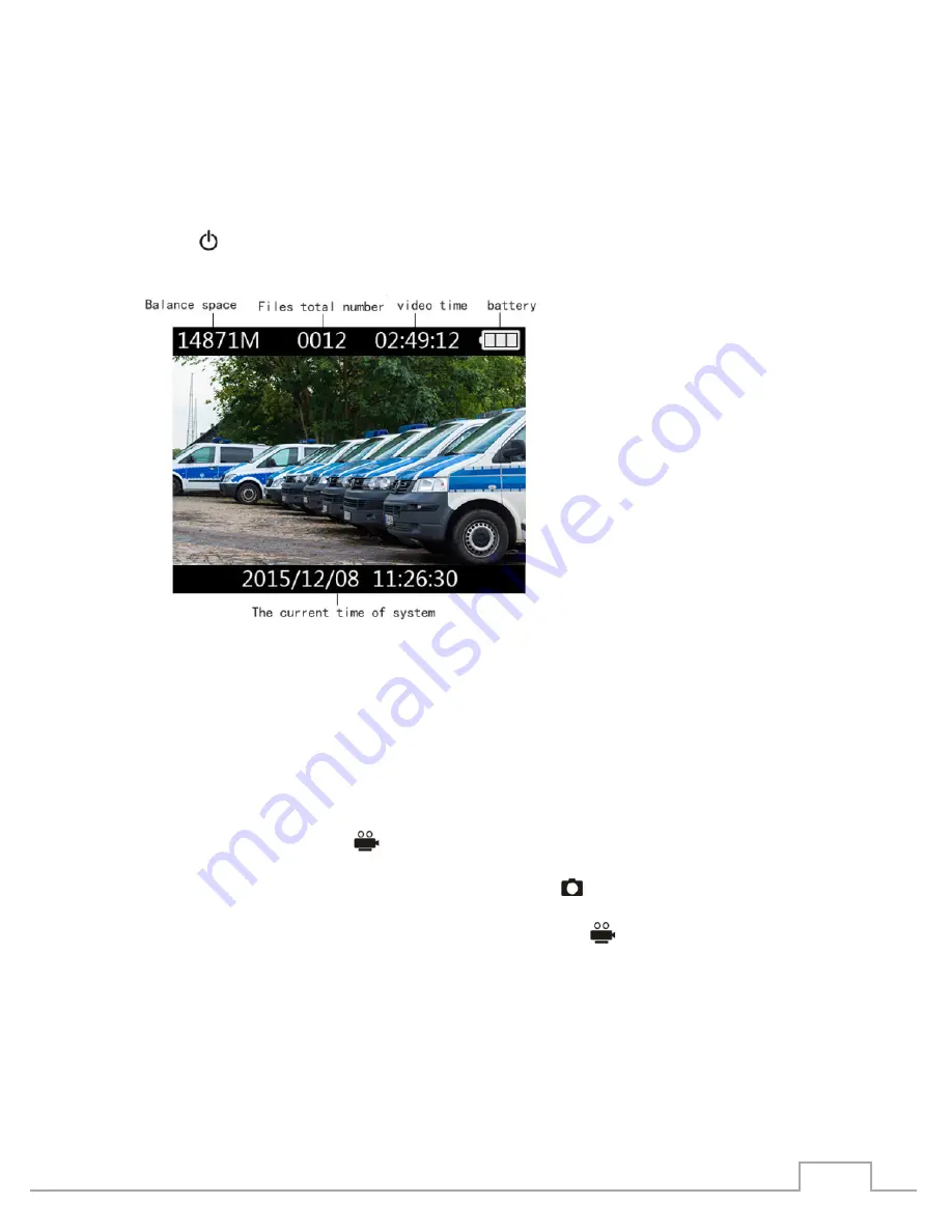
(Balance space, Files quantity, Available video recording time, Battery volume) 
 

In preview mode, you will see the balance space, the files quantity, the available video 
recording time, and the battery volume above the LCD screen from left to right. 
In the bottom of the screen you will be presented the current time of the system. 
 

5.2


Video Recording 

After the camera has been powered on, it will enter into preview mode automatically. Press 
the Video recording button

to start recording. You will hear a “beep” sound for 

confirmation and the status LED in front of the camera will turn red. A red status indicator 
will appear also on the display. Press the photo button

 to take photos while the video 

recording is on. The photos will be saved automatically in JPG format in the resolution of the 
video. To stop recording, press the video recording button 

again.  Two “beep” 

sounds will confirm that the recording has been stopped. The videos will be saved 
automatically in a H.264 compression format.  

Summary of Contents for GBW-G0116X

Page 1: ...Owner s Manual Body Worn Camera GBW G0116X 4 Megapixel Full HD IP68 Body Worn Camera ICR IR LED GBW G0116X 49 1 21 03 2016 ASP AG EN ...

Page 2: ......

Page 3: ...oto 9 6 4 Digital Zoom Function 9 6 5 Record Audio recording 10 6 6 IR Night vision 10 6 7 Playback mode 11 6 7 1 Select Playback File 11 6 7 2 Video Audio File Playback 11 6 7 3 Photo Playback 11 6 7 4 File Search 11 6 7 5 Exit the Playback Mode 12 6 8 Screen off 12 6 9 Standby Function 12 6 10 Walkie talkie 12 6 11 Trigger Automatic Video Function 12 6 12 Set the Vibration Function 13 6 13 Reset...

Page 4: ...e Instructions 15 7 5 1 Verify the Password 16 7 5 2 Re set the Password 16 7 5 3 Delete Files 17 7 5 4 Movable Disk 17 7 5 5 Recording Resolution 18 7 5 6 Segmented Time 19 7 5 7 Photo Resolution 19 7 5 8 IR 20 7 5 9 Screen off Time 20 7 5 10 Voice Prompt 21 7 5 11 Unit No 21 7 5 12 User No 21 7 5 13 Unit Name 22 7 5 14 User Name 23 7 5 15 Check the Equipment Information 23 8 Battery Recharging 2...

Page 5: ...EC battery directive This product contains a battery that cannot be disposed of as unsorted municipal waste in the European Union See the product documentation for the specific battery information The battery is marked with a Crossed out bin symbol which may include lettering to indicate cadmium Cd lead Pb or mercury Hg For proper recycling return the battery to your supplier or to a designated co...

Page 6: ... the inside of this device to rain or moisture 2 Package Contents These parts are included Body Worn Camera USB charging station USB charging cable USB data cable USB power supply Shoulder Strap Display protection foils 3 Key features 4 Megapixels CMOS Colour B W Camera Full HD 1080p resolution video recording IR LEDs integrated 170 viewing angle IP 68 Certification Built in 32GB SDRAM Video Image...

Page 7: ...kie Port Extension port 7 Photo key 8 Fixing Hole 9 Inter talk key 10 Playback 11 LCD turn off key 12 Power key 13 IR LED light 14 Status Indication LED 15 Lens 16 Inter talk MIC 17 Audio recording MIC Rotate to open the Cab Refer to the arrow in picture 18 Earphone port 19 HDMI Port 20 USB Port 21 Audio recording key 22 Menu Key ...

Page 8: ...rrent time of the system 5 2 Video Recording After the camera has been powered on it will enter into preview mode automatically Press the Video recording button to start recording You will hear a beep sound for confirmation and the status LED in front of the camera will turn red A red status indicator will appear also on the display Press the photo button to take photos while the video recording i...

Page 9: ...ed software Check the Use Management Software chapter for more details 5 3 Photo Press the photo button to take photos while the camera is in preview mode The photos will be saved automatically in JPG format in the resolution that was set using the management software 5 4 Digital Zoom Function This function is to activate the zoom in preview mode To Zoom Out press and hold the menu button again Th...

Page 10: ...opped Recording indication LED Recording time Battery volume Note While recording the audio the yellow status indication LED will flash and the red dot will flash in the left upper corner of the LCD screen 5 6 IR Night vision In preview mode or camera mode press and hold the display off button to start the IR mode Press and hold the display off button again to turn off the IR mode Enter the IR bri...

Page 11: ...tton to continue to play again Press the off button to return to thumbnail mode After the playback of the file has finished the camera will automatically return to thumbnail playback mode Note When replaying the video files press the video recording button to fast backward the video Press the photo recording button for fast forwarding the video 5 7 3 Photo Playback In thumbnail playback mode after...

Page 12: ...dby Function Set the standby time through the management software In standby mode the LCD screen will be shut down the yellow indicator will flash and the system will enter a standby power saving mode Press any function button to exit the power saving mode 5 10 Walkie talkie Use the interphone end that is connected to the cable to connect the camera s interphone interface and connect the other end...

Page 13: ...amera Document management system hereinafter referred to as document management system has high security tamper proof evidence documents functions etc It can realise such functions as device password modification time automatic synchronisation parameters setting of the resolution user information setting and important files uploading 7 2 Operation System The operating system supported by the softw...

Page 14: ... CD ROM of the camera into the upper drive open the CD run the driver and install the software Click on the Next button 7 3 2 Installation Path Select the installation path Click on the Next button 7 3 3 Create Shortcut Click on the Next button ...

Page 15: ...ish button to end the installation 7 4 Open the Management Software In the CD file click on the management software and run it 7 5 Management Software Instructions The camera needs to be connected with the upper machine through the USB cable and the management software needs to be executed The way to connect is shown in the figure below ...

Page 16: ...hronised with the upper computer s time Note The default password is 123456 please enter the password before executing any management software operation 7 5 2 Re set the Password To modify the password click on the reset password button to change the password Enter the correct former password input the new password twice and click on password confirmation After that a modified password success dia...

Page 17: ...to cancel this operation A confirmation dialogue will appear after that Note After completion of this operation the file shall be unrecoverable 7 5 4 Movable Disk To access the data stored on the camera press the movable disk button The computer will now detect the camera as a standard USB storage device and you will be able to access copy and delete all video files audio files and images which ar...

Page 18: ...ptions If you want to change the settings please disconnect the USB connection and reconnect again 7 5 5 Recording Resolution Here you can set the video resolution of the camera After selecting 2304 1296 30 1920 1080 60 1920 1080 30 1280 720 60 1280 720 30 848 480 30 click on Recording Resolution ...

Page 19: ...tation time that will be used for video recordings After choosing the 5 minutes 10 minutes 15 minutes 30 minutes and off click on segmented time 7 5 7 Photo Resolution After choosing 7680X4320 6016X3384 5376X3024 2688X1512 click on Photo Resolution ...

Page 20: ...R mode with the dedicated button Under auto mode the camera will switch automatically to BW IR mode After choosing between manual or automatic option click the IR button 7 5 9 Screen off Time You can set the screen off time of the Camera After choosing 1 minute 5 minutes click on screen off time ...

Page 21: ...l be implemented in the video recording Enter the unit number and click on the unit number button A dialogue will appear that the unit number has been changed successfully Note The unit number length cannot be more than 12 digits and can only consist of numbers or characters 7 5 12 User No You can set the user No to the camera and superimpose the user information on the video image file ...

Page 22: ...Note The User No length cannot exceed 6 digits and can only consist of numbers or characters 7 5 13 Unit Name You can set the unit name in the camera Enter the unit name and click on the unit name button A dialogue will appear that the unit number has been changed successfully Note the unit name length can t be more than 32 characters ...

Page 23: ...ppear that the unit number has been changed successfully Note The user name length cannot be more than 32 characters 7 5 15 Check the Equipment Information When you click on check the equipment information the following information can be displayed device serial number user No user name unit number unit name and other information ...

Page 24: ...the recorder will startup automatically and enter into charging mode In the charging process the status indicator light will show red After the full charge the indicator light will turn green The charging time to full capacity is ca 8 hours using the power adapter Note It is recommended to charge in shutdown state 8 3 Multifunctional Charging Base Use the included power cables to connect the power...

Page 25: ... for a long time off in order to avoid battery failure 9 How to Wear the Shoulder Strap Wearing Method I 1 Spread the Shoulder Strap and insert it from the bottom to the top of the shoulder mark 2 When reaching the top of the Shoulder Strap reverse it back 3 Pass the reversed part through the middle tier of the shoulder strap 4 Press the buckle to fix the straps bayonet in the fixed position of th...

Page 26: ...ing Method II 1 Open the shoulder straps insert itunder the shoulder board 2 Reverse the upper straps 3 Cover the reversed part on the shoulder part and fix the clip mouth 4 Put the back clip on the built in button of the adaptor press the buckle to fix the straps 5 Turn the regulator to adjust it to the appropriate location ...

Page 27: ... Compression ADPCM WAV Image Size 2592x1944 3200x2400 4608x3456 5210x3840 by Software upscaling Video Text Overlay 15 character 1 lines Digital Zoom 8x White Balance ATW DIS Digital Image Stabilisation yes Access protection Password Audio Inputs Built in Microphone Audio Outputs Built in Speaker Phone Jack 2 5mm SD memory 32GB built in Display 2 LCD 960x240 pixels LED Indicator Power Video Recordi...

Page 28: ...8 EC Low Voltage Directive 2006 95 EC Applied harmonised standards and technical specifications EN 55022 2010 Class B EN 55024 2010 EN 61000 3 2 2006 A1 2009 A2 2009 EN 61000 3 3 2008 EN 61000 4 2 2008 EN 61000 4 3 2010 EN 61000 4 4 2004 A1 2010 EN 61000 4 5 2005 EN 61000 4 6 2008 EN 61000 4 8 2009 EN 61000 4 11 2004 ASP AG Lüttringhauser Str 9 42897 Remscheid Germany Remscheid 17 01 2012 Ludwig B...

Reviews: