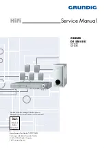
GRUNDIG Service
CINEMO DR 5400 DD
1 - 2
Table of Contents
Page
General Section ................................ 1-2 … 1-11
Measuring Instruments / Equipment ............................................ 1-2
Technical Data ............................................................................. 1-3
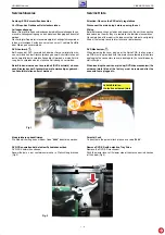
Service Hints ................................................................................ 1-4
Operating Hints ............................................................................ 1-9
Layout of PCBs
and Circuit Diagrams ....................... 2-1 … 2-23
Wiring Diagram ............................................................................ 2-1
Main PCB ..................................................................................... 2-2
- Power Supply ........................................................................... 2-2
- MCU ......................................................................................... 2-3
- Amplifier Part ............................................................................ 2-4
- PCB .......................................................................................... 2-5
Subwoofer-Amplifier ..................................................................... 2-8
- Circuit Diagram ........................................................................ 2-8
- PCB .......................................................................................... 2-9
Front Panel ................................................................................ 2-10
- Circuit Diagram ...................................................................... 2-10
- PCB ........................................................................................ 2-11
MPEG Board .............................................................................. 2-12
- Circuit Diagram ...................................................................... 2-12
- PCB ........................................................................................ 2-19
Exploded Views and
Spare Parts List .................................. 3-1 … 3-4
Exploded View ............................................................................. 3-1
Spare Parts List ........................................................................... 3-2
Inhaltsverzeichnis
Seite
Allgemeiner Teil ................................. 1-2 … 1-8
Messgeräte / Messmittel .............................................................. 1-2
Technische Daten ........................................................................ 1-3
Servicehinweise ........................................................................... 1-4
Bedienhinweise ............................................................................ 1-6
Platinenabbildungen
und Schaltpläne ............................... 2-1 … 2-23
Verdrahtungsplan ......................................................................... 2-1
Haupt-Platte ................................................................................. 2-2
- Netzteil ..................................................................................... 2-2
- MCU ......................................................................................... 2-3
- Verstärkerteil ............................................................................ 2-4
- Leiterplatte ............................................................................... 2-5
Subwoofer-Verstärker .................................................................. 2-8
- Schaltplan ................................................................................ 2-8
- Leiterplatte ............................................................................... 2-9
Front-Platte ................................................................................ 2-10
- Schaltplan .............................................................................. 2-10
- Leiterplatte ............................................................................. 2-11
MPEG-Platte .............................................................................. 2-12
- Schaltplan .............................................................................. 2-12
- Leiterplatte ............................................................................. 2-19
Explosionszeichnungen und
Ersatzteilliste ...................................... 3-1 … 3-4
Explosionszeichnung ................................................................... 3-1
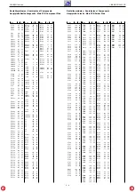
Ersatzteilliste ................................................................................ 3-2
Allgemeiner Teil
Messgeräte / Messmittel
Mess-Sender
Oszilloskop
Digitalvoltmeter
Trenntrafo
General Section
Measuring Instruments / Equipment
Signal generator
Oscilloscope
Digital voltmeter
Isulating Transformer
Summary of Contents for Cinemo DR 5400 DD
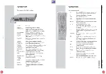
Page 7: ...GRUNDIG Service CINEMO DR 5400 DD 1 7 ...
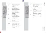
Page 8: ...GRUNDIG Service CINEMO DR 5400 DD 1 8 ...
Page 10: ...GRUNDIG Service CINEMO DR 5400 DD 1 10 ...
Page 11: ...GRUNDIG Service CINEMO DR 5400 DD 1 11 ...
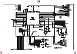
Page 19: ...GRUNDIG Service CINEMO DR 5400 DD 2 8 Subwoofer Verstärker Subwoofer Amplifier ...
Page 21: ...GRUNDIG Service CINEMO DR 5400 DD 2 10 Front Platte Front Panel ...
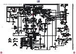
Page 23: ...GRUNDIG Service CINEMO DR 5400 DD 2 12 MPEG Platte MPEG Board ...
Page 24: ...GRUNDIG Service CINEMO DR 5400 DD 2 13 MPEG Platte MPEG Board ...
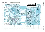
Page 25: ...GRUNDIG Service CINEMO DR 5400 DD 2 14 MPEG Platte MPEG Board ...
Page 26: ...GRUNDIG Service CINEMO DR 5400 DD 2 15 MPEG Platte MPEG Board ...
Page 27: ...GRUNDIG Service CINEMO DR 5400 DD 2 16 MPEG Platte MPEG Board ...
Page 28: ...GRUNDIG Service CINEMO DR 5400 DD 2 17 bis Seriennumm up to serial num MPEG Platte MPEG Board ...

