5
Eng
lish (
U
S)
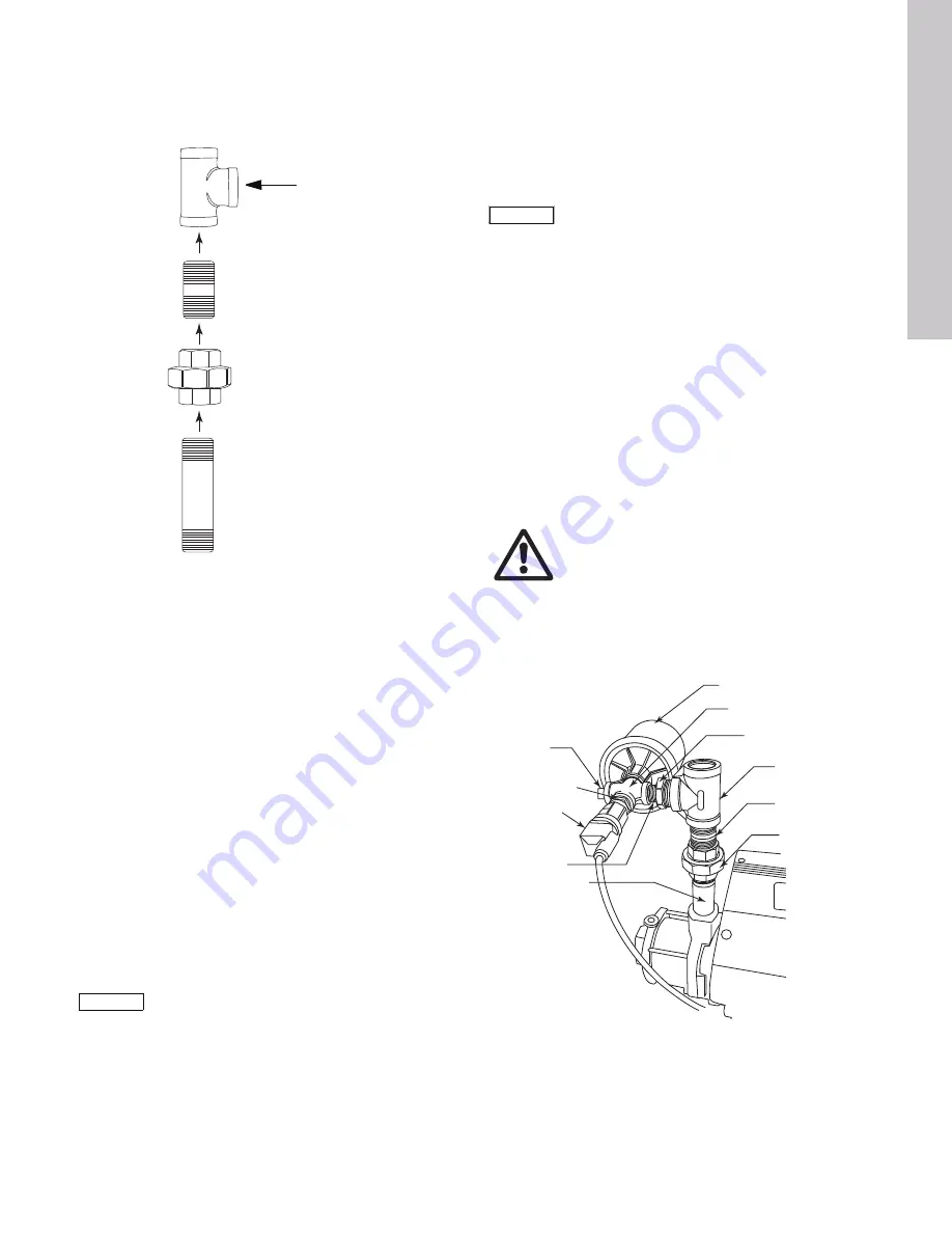
7. Thread the tank/transducer manifold assembly to discharge
tee as shown in fig. 7. Tighten wrench tight.
8. Tighten the cross fitting such that the transducer, plug and
bushing(s) are positioned horizontally. Tighten wrench tight.
Fig. 7
Threading tank/transducer manifold assembly to
discharge tee
5.3 Attach the tank
1. Remove the plastic protective cover from over the tank
threads. Confirm the O-ring is in place and thread the tank into
the final port in the 1/2” NPT cross fitting opposite the
pressure transducer. Tank should now also be horizontal.
Tighten until hand tight.
2. The tank is pre-charged from the factory to 50 psi (+/- 7 psi)
and may need to be adjusted for optimum pump performance.
Tank pre-charge pressure must be 0.7 x actual setpoint.
49 psi is the correct pre-charge setting for a 70 psi setpoint
(70 x 0.7 = 49).
6. Install the pump
1. Install the pump according to the CM and CME Installation and
Operating Instructions with these additional steps:
– Wrap 3 to 4 turns of Teflon tape on the male threads of the
suction size pipe nipple.
– Thread the suction sized pipe nipple directly in the pump
inlet fitting.
– Thread the check valve onto the pipe nipple; tighten until
wrench tight.
2. Connect the main power cable and pressure transducer cable
to the motor terminal box according to the CME Installation
and Operating Instructions supplied with the pump.
6.1 Set the pump parameters
Using an R100 remote programmer, set the following parameters:
• SENSOR TYPE: As per the label on the transducer (typically
4-20 mA and range 0-87 psi (0-6 bar) or 0-145 psi (0-10 bar))
• STOP FUNCTION:Active
• CONTROL MODE:Controlled
6.2 Perform functional test
Start the pump and perform the following functional test including
monitoring for leaks and watching for any obvious problems:
1. Reduce the setpoint to the second LED light from the bottom
on the motor control panel by pressing the DOWN arrow as
many times as necessary.
2. Slowly close the discharge line valve and observe that the
motor reduces speed to compensate for the lower flow rate.
3. Fully close the discharge line valve to test the motor stop
function. (The motor should stop within approximately
2 minutes if there are no leaks).
Note: The stop function may not operate properly, if the
setpoint requires 90% to 100% of the motor maximum speed
or if the diaphragm tank pre-pressure is not in the desired
range
.
4. Fully open the discharge line valve and observe that the pump
starts again.
5. The pump is ready for its normal operation now. Please see
the CME Installation and Operating Instructions supplied with
the pump for further instructions.
Fig. 8
Completed kit assembly
T
M
05 06
52 13
11
Note
Note
If you purchased a complete CME-Plus from
the factory, the pressure transducer and R100
settings are already installed
.
Thread tank/transducer
manifold assembly here
Note
Note
Pump must be primed before functional test.
Warning
After setting your pump setpoint, be sure that
you have not inadvertently set the pump to run on
Max Curve
,
Min Curve
or
Stop
. See the CRE,
CRIE...CME Installation and Operating
Instructions for more information.
T
M
05 0
659 1
41
1
Tank with O-ring
1/2" NPT cross fitting
1/2" to discharge
size bushing
Discharge
tee
1/2" NPT
plug
1/4" to 1/2"
NPT bushing
Transducer
1/2" NPT
pipe nipple
Discharge
nipple
Discharge
union
Discharge
pipe
CME Plus Kit Assembly I&O.book Page 5 Thursday, April 7, 2011 4:41 PM


