


GRT Avionics, Inc.
May 2019
Sport SX Install. Manual
14
Rev. A
*NOTE:
The most common cause of magnetic sensing error is simply magnetic
disturbances near the magnetometer. This can be caused by ferrous metal (any metal
that a magnet will stick to), control cables or cable carrying electrical currents, such as
navigation or
landing lights, being too close to the magnetometer. The magnetometer’s
location will be tested for interference in
Section 5: Initial Checkout, Basic
Configuration Settings and Calibration
, after the initial boot-up checks of the Sport SX.
3-3: Legacy Analog Magnetometer Installation for Sport
SX200
Determining the location of the magnetometer requires considerable care because of the
magnetometer's sensitivity to magnetic disturbances generated by the airplane. No
periodic maintenance is required for the magnetometer, although it is desirable to mount
it in a location that allows access to it if necessary. The most important consideration
when mounting the magnetometer is choosing a location in the airplane that is away from
magnetic disturbances. It is quite amazing how sensitive the magnetometer is to these
disturbances and how much error this can cause in the magnetic heading reported by the
AHRS.
Keep the magnetometer at least 12 inches away from any current carrying wires (such as
navigation or landing light wires) and more than 18 inches from ferrous metal, such as
the steel mass balance tube that is typically used in the leading edge of ailerons. Use
non-ferrous hardware (or even double-sided sticky tape) for mounting the magnetometer.
You can test your proposed magnetometer location prior to mounting the magnetometer
itself by placing an ordinary compass at the spot. Then:
1. Turn on and off any electrical equipment whose wiring passes within 2 feet of the
proposed magnetometer location.
2. Move the flight controls from limit to limit.
3. If the proposed magnetometer location is within 2 feet of retractable landing gear,
operate the landing gear.
Observe the compass while doing each of the above processes. The goal is for there to
be no movement from the compass needle, although movement of less than five degrees
is acceptable. If you observe the needle moving greater than five degrees at any time, try
another location. After the installation and wiring of the magnetometer and display unit(s)
is complete, a more sensitive check for magnetic disturbances will be conducted.
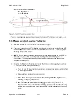
The magnetometer and the AHRS in the Primary Flight Display unit work together. For
this reason, they must be oriented in the same direction; that is, the pitch, roll and yaw
axes of the magnetometer and the PFD display unit containing the AHRS need to be
parallel. A standard level can be used to orient the magnetometer and display unit such
that they are equal in roll and pitch. For yaw, the orientation of these devices should be


