

5
Revision date: 01.28.20
ASSEMBLE DOOR FRAME COMPONENTS (continued)
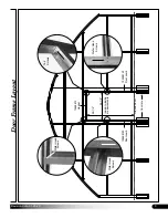
Door Frame Assembly
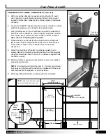
Cut along
dotted lines.
Bend this
section inward
Door
Header
F
G
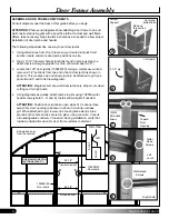
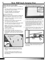
5. With door jambs attached, measure and mark height of rough
door opening.
Consult drawing below and Door Frame Layout
located in Quick Start
. Measure from finished grade to underside
of header.
6. Locate the 10548872 header material, measure
outside-to-outside
width of door jambs, and cut header to required length.
7. Using a metal saw, cut two 2" sections and bend lip inward from
both ends of door header as shown at right (see photos F and G).
This creates two (2) tabs and allows header to attach to jambs.
Open channel of header points upward.
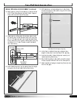
8. Position header so the two (2) tabs on each side overlap door
jambs (see photo H). Align header bottom with vertical support
marks made in Step 5. Ensure header is level and check
dimensions.
9. Attach front and back of header to jambs using wafer head
screws. Reinforce header by securing bent lip to vertical support
using Tek screws as shown in photo H. (Customer-supplied bolts
can also be used.)
10. After door frame is square and assembled, secure door jambs in
ground using concrete.
NOTE:
Concrete should remain at least 2"- 4" below ground level
so it does not interfere with construction, installation of other end
wall components (if equipped), or door operation.
11. After assembling door frame, continue with door assembly.
H
H
Concrete
Ground Level
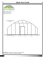
48-1/2"
92-1/2"
(inside-to-inside)
Door jamb
in concrete.
Ground
Level
*Not to
scale.
NOTE:
Sample end frame and rafter
are not included with any door kit.
10548872
Header (cut to length)
(inside-to-inside)
Step 6
(outside-to-outside)
Wafer
Head
Screws
Tek screw
TOP VIEW
H