background image

59

13 

Contact 

If you have technical problems about our products, contact the GROWATT Serviceline. 
We need the following information in order to provide you with the necessary 
assistance:

Inverter type
Serial number of the inverter
Event number or display message of the inverter
Type and number of PV modules connected
Optional equipment


Growatt USA,Inc

9227 Reseda Blvd,#435 Northridge,CA 91324,USA.


+

818


800-9177

www.growatt-america.com

T
E    

[email protected]

W

Summary of Contents for MIN 3000TL-XH-US

Page 1: ...00 GR UM 210 A 00 Installation Operation Manual Download Manual Growatt New Energy Growatt USA Inc 9227 Reseda Blvd 435 Northridge CA 91324 USA 818 800 9177 www growatt america com T E usaservice ginv...

Page 2: ...2 5 DC and AC disconnect 2 6 Grounding the PV modules 2 7 Appropriated Usage 2 8 Operation Warnings 3 Product description 4Inspection of delivery 5 Instruction 5 1 5 2 5 3 5 4 Safety instruction Selec...

Page 3: ...system LED description 7 4 Powering off the system 7 5 Button 12 1 Specification 12 2 Efficiency curve 8 1 8 2 Overview APP Download 8 3 APP Login page 8 4 Connecting to the inverter local Wi Fi netwo...

Page 4: ...ui si elle n est pas vit e est susceptible de provoquer un d c s ou des blessures graves WARNING indicates a hazardous situation which if not avoided could result in death or serious injury AVERTISSEM...

Page 5: ...after receiving appropriate approvals as required by the local authority having jurisdiction The GROWATT TL XH US Inverters is designed and tested according to international safety requirements UL1741...

Page 6: ...ungrounded conductors after installation 2 4 Certified countries 2 5 DC and AC disconnect 2 6 Grounding the PV modules 2 7 Appropriated Usage 2 7 1 Assembly Warnings The MIN TL XH US series product i...

Page 7: ...zard to minimize occurrence of such conditions comply with all corresponding safety symbols and markings present on the unit and in this manual Ensure all covers and doors are closed and secure during...

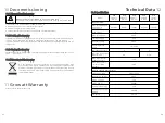
Page 8: ...e pas retirer la protection jusqu 5 minutes apr s avoir d connect toutes les sources d nergie Risque de choc lectrique Les conducteurs normalement terre doivent tre enterr s et aliment s lorsqu une fu...

Page 9: ...PV side The inverter is thoroughly tested and strictly inspected before delivery Our inverters leave our factory in proper electrical and mechanical condition Special packaging ensures safe and carefu...

Page 10: ...can become very hot Touching the surface can result in burns Do not touch hot surfaces During operation do not touch any parts other than the lower enclosure lid of the inverter Mount the inverter in...

Page 11: ...ower reduction Observe the Min clearances to walls other inverters or objects as shown below 300mm 12inch Ambient dimensions of one inverter Ambient dimensions of series inverters There must be suffic...

Page 12: ...f the wiring box as shown below 1 RemoveRemove the cover 2 Open the required AC AC DC and COM conduit drill guides according to the conduits used in the installation The drill guides are located at th...

Page 13: ...y remove the unit from its packaging and inspect for external damage If you find any imperfections please contact your local dealer 3 Be sure that the inverters connect to the ground in order to prote...

Page 14: ...DC power to inverter If using MIN TL XH US series PV inverter With Arc fault current detection function we recommend consumer connect the Tracker A and Tracker B to different PV module strings Conver...

Page 15: ...d V Temp coefficient to ensure PV string voltage is less than 600 Vdc Maximum inverter PV input voltage for all possible weather conditions in the location of installation Use only solid or stranded w...

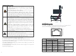
Page 16: ...ng AC Grounding Grounding Electrode Terminal GET It must be connected to the AC grounding conductor of the power distribution grid via the ground terminal PE The AC input and AC output circuits are is...

Page 17: ...L2 of Backup Insert the cable into the round opening and remove the screwdriver then the cable is automatically clamped Connect the PE to the Grounding terminal Keep the wiring box clean Fig 6 12 Fig...

Page 18: ...ll guide that was opened Insert the 0 6 3 5 mm standard flat blade screwdriver and press the release mechanism and open the clamp Connect the cable to the appropriate terminal blocks according to the...

Page 19: ...nverter and the battery Since the inverter is transformer less the battery connected to the inverter cannot be grounded ensure that the battery output is well insulated to ground The cable distance be...

Page 20: ...ation board Keep the wiring box clean Fig 6 19 The energy meter connection is required to get information about energy flow Before connecting the energy meter to this product install the energy meter...

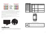
Page 21: ...he 6 pin RS485 terminal block connector Insert the wires into the RS485A2 GND RS485B2 pins shown below Use four or six wire twisted pair cable for this connection The same color wire is used for all A...

Page 22: ...al 100Base TX Signal T568B T568A 1 White Orange White Green Transmit 2 Orange Green Transmit 3 White Green White Orange Receive 4 Blue Blue Receive 5 White Blue White Blue Receive 6 Green Orange Recei...

Page 23: ...ry cable and signal cable are connected correctly securely and reliably 8 Unused terminals and ports Unused terminals and ports are fitted with waterproofing bolts or watertight caps 9 Cable routing p...

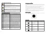
Page 24: ...ink 1s on 1s off BAT internal comm Fai COMM Green Blink 7 4 Powering off the system 7 5 Button 7 5 1 Reset button Send a shutdown command from the APP for details see the Operations on the Shinephone...

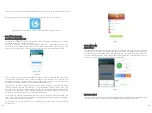
Page 25: ...directly it is used for Local Tool 8 1 Overview Operations on the Shinephone APP 8 Fig 8 1 Mobile phone connecting to the inverter local WiFi The mobile phone connects to the MIN TL XH US inverter th...

Page 26: ...eChat and QQ In addition in the ShinePhone above version 4 95 the function of remembering multiple account passwords has been implemented After the user logs in successfully the next time you log in y...

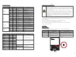
Page 27: ...rter local Wi Fi is represented by its serial number SN the SN can be found on the label on the left side of the inverter enclosure Enter the Wi Fi password to establish a connection 8 4 Connecting to...

Page 28: ...PV panel Output power of the panel Voc of the panel Vmp of the panel Imp of the panel Number of panels in each string If it is necessary to replace the unit please ship it in the original box System f...

Page 29: ...exist please contact Growatt customer service to replace the M3 board Warning405 Firmware version is not consistent Uptate the right version firmware Error code Meanings Suggestion Error 402 Output H...

Page 30: ...size of the inverter 1 Disconnect the inverter as described in section 6 2 Remove all connection cables from the inverter 3 Screw off all projecting cable glands 4 Lift the inverter off the bracket a...

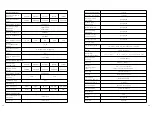
Page 31: ...97 97 50 97 50 98 Protection devices DC reverse polarity protection Integrated DC switch Integrated DC Surge protection Type II AC surge protection Type III AC short circuit protection Integrated Gro...

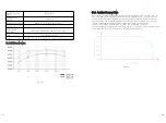
Page 32: ...XH US series inverter operate at full power and full currents up to a certain temperature above which they may operate with reduced ratings to prevent device damage The following diagram illustrates...

Page 33: ...order to provide you with the necessary assistance Inverter type Serial number of the inverter Event number or display message of the inverter Type and number of PV modules connected Optional equipme...

Reviews: