background image

1


Notes on this manual

1.1 Validity

1

2

1.2 Target Group

This  manual  is  for  qualified  personnel.  Qualified  personnel  have  received  training  and 
have  demonstrated  skills  and  knowledge  in  the  construction  and  operation  of  this 
device. Qualified Personnel are trained to deal with the dangers and hazards involved in 
installing electric devices.

1.3 Additional information

Find  further  information  on  special  topics  in  the  download  area  at  www.ginverter.com 
The  manual  and  other  documents  must  be  stored  in  a  convenient  place  and  be 
availableat all times. We assume no liability for any damage caused by failure to observe 
these instructions. For possible changes in this manual, Shenzhen Growatt New Energy 
CO.,LTDaccepts no responsibilities to inform the users.

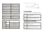
1.4.2 Markings on this product

1.4 

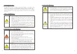
Symbols in this document

A warning describes a hazard to equipment or personnel. It calls attention to a procedure 
or practice, which, if not correctly performed or adhered to, could result in damage to or 
destruction of part or all of the Growatt equipment and/or other equipment connected 
to the Growatt equipment or personal injury.

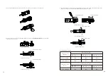
This manual describes the assembly, installation, commissioning and maintenance of the 

following Growatt Inverter model:

MIN 2500 TL-XA

MIN 3000 TL-XA

MIN 3600 TL-XA

MIN 4200 TL-XA

MIN 4600 TL-XA

MIN 5000 TL-XA

MIN 6000 TL-XA

CAUTION

NOTICE

 is used to address practices not related to personal injury.

Information

 that you must read and know to ensure optimal 

operation of the system.

NOTICE

Information

WARNING

DANGER

Symbol

Description

DANGER


indicates a hazardous situation which, if not avoided, will 

result in death or serious injury.

WARNING

 indicates a hazardous situation which, if not avoided, could 

result in death or serious injury.

CAUTION

 indicates a hazardous situation which, if not avoided, could 

result in minor or moderate injury.

Symbol

Explanation

Electrical voltage

Risk of fire or explosion

Risk of burns

Wait for 5minutes before engaging in the indicated action

Point of connection for grounding protection

Direct Current (DC) 

Alternating Current (AC)

The inverter has no transformer

Read the manual

CE mark

The  inverter  complies  with  the  requirements  of  the  applicable  CE 

guidelines

Discard this product according to local regulations

1.4.1 Warings in this document

This manual does not cover any details concerning equipment connected to the MIN TL- 
XA. Information concerning the connected equipment is available from


the 

manufacturer of the equipment.

Summary of Contents for MIN 2500TL-XA

Page 1: ...IN 4600TL XA MIN 5000TL XA MIN 6000TL XA GR UM 257 A 00 Download Manual Growatt New Energy Shenzhen Growatt New Energy Co Ltd 4 13 F Building A Sino German Europe Industrial Park Hangcheng Ave Bao an...

Page 2: ...on of skilled person 2 3 Safety instruction 2 4 Assembly Warnings 2 5 Electrical Connection Warnings 2 6 Operation Warnings 1 1 Validity 1 2 Target Group 1 3 Additional information 1 4 Symbols in this...

Page 3: ...nnectors info 14 3 Torque 14 4 Accessories 6 Electrical connection 13 Decommissioning 7 Commissioning 14 Technical Data 7 1 Start the inverter 7 2 General setting 7 3 Advanced setting 7 4 Communicatio...

Page 4: ...es the assembly installation commissioning and maintenance of the following Growatt Inverter model MIN 2500 TL XA MIN 3000 TL XA MIN 3600 TL XA MIN 4200 TL XA MIN 4600 TL XA MIN 5000 TL XA MIN 6000 TL...

Page 5: ...r The external wireless communication does not require line of sight between the devices and it is selective purchasing Safety 2 The unit converts the DC current generated by the battery BAT to grid c...

Page 6: ...of accidents Systems with inverters typically require additional control e g switches disconnects or protective devices e g fusing circuit breakers depending upon the prevailing safety rules DANGER E...

Page 7: ...off 0 5s on 2S off programming Yellow 1s on and 1s off The type labels provide a unique identification of the inverter The type of product Device specific characteristics Certificates and approvals T...

Page 8: ...imensions and weight 10 9 Model Name MIN 2500 TL XA MIN 3000 TL XA MIN 3600 TL XA DC nominal input voltage 400V DC input voltage range 360 500V 360 500V 360 550V DC Max input output current 17A AC nom...

Page 9: ...regulations for the complete system All electrical installations shall be done in accordance with the local and national electrical codes Do not remove the casing Inverter contains no user serviceabl...

Page 10: ...oids forward and sideways tilt Be sure that the inverter is out of the children s reach Don t put any things on the inverter Do not cover the inverter Do not install the inverter near television anten...

Page 11: ...d leave 2 to 4mm exposed Falling equipment can cause serious or even fatal injury never mount the inverter on the bracket unless you are sure that the mounting frame is really firmly mounted on the wa...

Page 12: ...XA MIN 6000 TL XA The AC wiring step 1 Uninstall the parts of the AC connection plug from the accessory bag 2 Insert the stripped and bared cable through pressure screw seal ring threaded sleeve in s...

Page 13: ...then pull it out Wire suggestion length Conductor cross section Max cable length MIN 2500 TL XA MIN 3000 TL XA MIN 3600 TL XA 4 mm 12AWG 48m 40m 33m 5 2 mm 10AWG 60m 50m 42m Conductor cross section Ma...

Page 14: ...erable damage to the inverter Only qualified personnel can perform the wiring work WARNING WARNING 6 3 Connecting the second protective conductor In some installation countries a second protective con...

Page 15: ...um ion battery pack is not properly connected or the electrical disconnection will cause the equipment to work abnormally or even damage the equipment 6 5 Connecting signal cable This series inverter...

Page 16: ...ower output levels of an inverter The export limit control function for an inverter is used to control the generation from an inverter to manage the export power level from an electrical installation...

Page 17: ...RM6 DRM7 DRM8 are available Damage to the inverter due to moisture and dust penetration Make sure the cable gland has been tightened firmly If the cable gland are not mounted properly the inverter can...

Page 18: ...age the inverter External voltage of PCI PORT don t over 5V WARNING 6 8 1 2 Method of asserting demand response modes RRCR PCI Connector 6 8 2 1 8Pin socket pin assignment Pin Description Connect to R...

Page 19: ...ther region after 30s When inverter powered on OLED will light automatically Once the BAT power is sufficient OLED displays the following Press the touch key once a second to scroll through the differ...

Page 20: ...2019 04 18 Double touch Date Setting 20NN 04 18 Double touch Double touch Date Setting 20NN 04 18 Multiple single touch Date Setting 20NN NN 18 Double touch Multiple single touch Date Setting 20NN NN...

Page 21: ...e touch ExportLImit Rate 000 0 ExportLImit Rate 0N0 0 Double touch Multiple single touch ExportLImit Rate 0N0 0 ExportLImit Rate 0NN 0 Multiple single touch Set OK Double touch Double touch ExportLImi...

Page 22: ...Disable LoadFirst 00 01 Time1 Enable Multiple single touch Multiple single touch Multiple single touch Double touch Double touch Double touch Double touch Double touch Double touch Single touch Single...

Page 23: ...5A2 Connect Min ShineBus or third party monitoring equipment 7 BAT B Connect the BAT communi cation RS485B or CANL 4 RS485B2 Connect Min ShineBus or third party monitoring equipment 8 BAT A Connect th...

Page 24: ...issipation 9 2 Cleaning the Inverter 9 3 Checking the DC Disconnect If the inverter regularly reduces its output power due to high temperature please improve the heat dissipation condition Maybe you n...

Page 25: ...by system instead of inverter please check the items as instructed below before replacing inverter Error message Description Suggestion Residual I High Error 201 Leakage current too high Restart the...

Page 26: ...7 The data sampled by the DSP and redundant M3 is not the same 1 Restart inverter 2 I f problem still exist contact Growatt Error 420 GFCI fault 1 Restart inverter 2 I f problem still exist contact Gr...

Page 27: ...HDi 3 AC grid connection type Single phase L N PE AC overvoltage category Category III Model Specifications MIN 2500 TL XA MIN 3000 TL XA MIN 3600 TL XA MIN 4200 TL XA AC input quantities Nominal AC i...

Page 28: ...m continuous 17A DC output quantities Nominal DC output voltage 400V DC output voltage range 360 550V DC output current maximum continuous 17A Battery type Cobalt Free Lithium Iron Phosphate LFP AC ou...

Page 29: ...monitoring Integrated Anti islanding protection Integrated Active Frequency Drift Residual current monitoring unit Integrated General data Dimensions W H D in mm 375 350 160 Weight 9 1 kg Operating te...

Page 30: ...nfo 14 3 Torque BAT connectors VP D4B CHSM0B VP D4B CHSF0B AC connector VPAC06EP 3S SC 5 EN032 1128 1001 VPAC06EW 3P SC Enclosure lid screws 12kgf cm AC terminal 6kgf cm Signal terminal 4kgf cm M6 sok...

Reviews: