

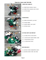
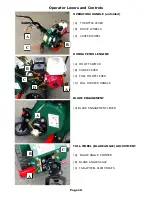
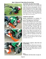


OPERATORS HANDLES
The operators handles ’A’ can be folded for
storage or carriage.
To unfold slacken handle
clamp lever ’B’ and pivot the handles ‘A’ up and
back. Set the operators handles at a height which
is comfortable to operate the machine when the
blade is in the ground. Re-tighten the clamp lever
firmly.
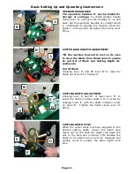
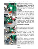
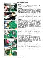
CUTTER BLADE DEPTH ADJUSTMENT
Tilt the machine forward to rest on its nose
to clear the Blade from the Ground to enable
In and Out of Work and Cutting Depth ad-
justments.
Out Of Work
Unclamp lever ‘A’ and lift lever ‘B’ to raise the
blade out of work for transport.
CUTTING DEPTH ADJUSTMENT
Unclamp lever ‘A’ and lift or lower lever ‘B’ to
select the desired cutting depth 0 to 3 inches by
aligning holes ‘E’ with the depth indicator arrow
on decal ‘D’ Tighten the depth clamp lever ‘A’
firmly.
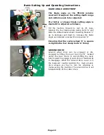
CUTTING DEPTH STOP
When the cutter blade has been adjusted to the
desired cutting depth, loosen the depth stop
clamp nut ‘G’ and slide the depth stop down the
slot to the stop and re-clamp. This enables the
blade to be raised out of work for transport and
quickly re-set to exactly the same depth each
time.
A
B
A
B
A
Page 11
Basic Setting Up and Operating Instructions
B
D
F
E
G
F
E


