background image


- 19 -


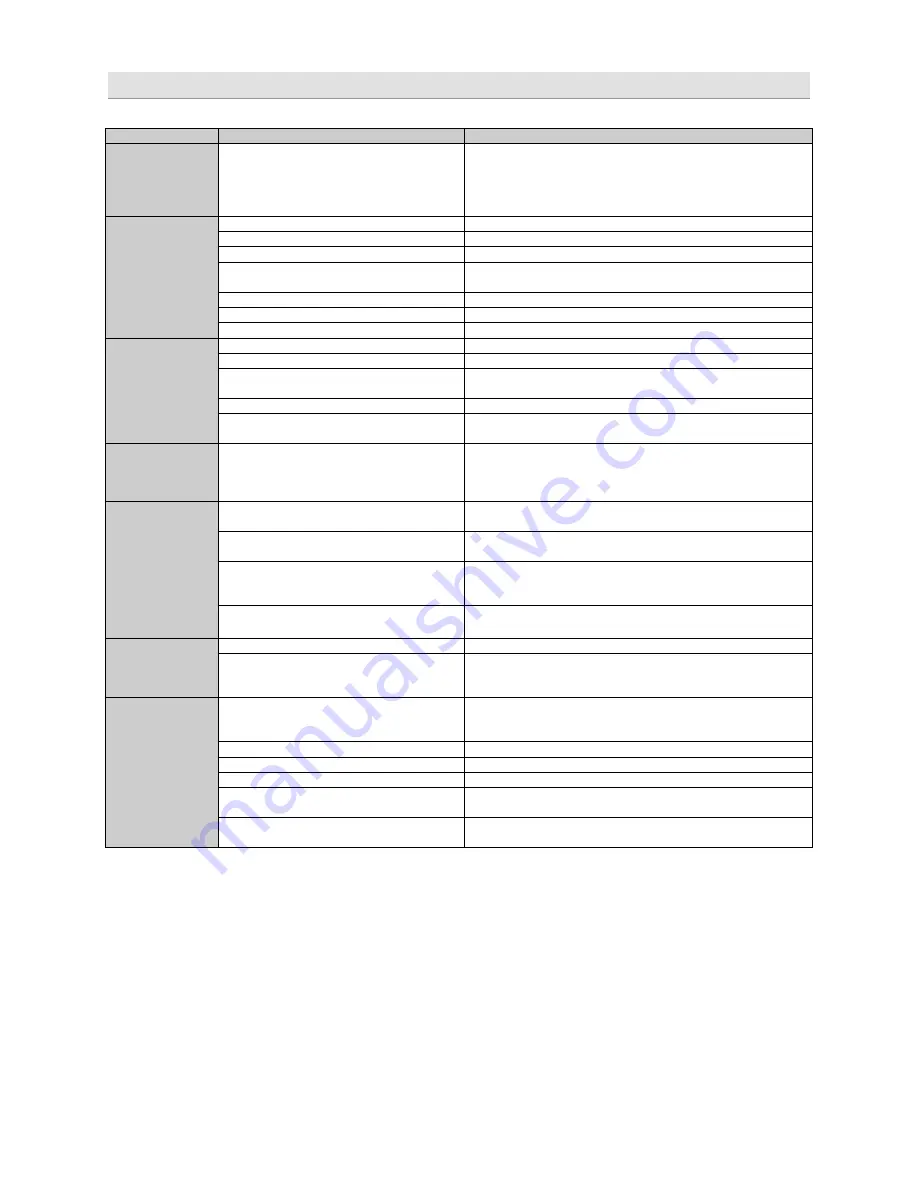
Error diagnosis 


Error 

 Control 

Help / Solution 

No function 

 PWR LED on? 

check the fuse(s) 
check the remote wire (not required in high-level mode) 
check the auto-on switch position (in high-level mode) 
check the +12 Volt connection and wire 
check the ground connection and wire 

No sound 

(PWR LED on) 

no setup selected 

select the setup using the DSP software 

signal wire no contact or broken 

check the contact or replace the wire 

no audio signal from the head-unit 

check the audio output signal of the head-unit 

non-operational further amplifier  

check the remote wire connection (if used) 
check the further amplifier´s power supply 

non-operational source is selected 

check the source unit 

MUTE function activated (software) 

check the setup using the DSP software 

level at optional remote control is too low 

check the setting at the remote control 

Single channels 

with no function 

signal wire has no contact or it´s broken 

check the contacts or replace the wire 

no audio signal from the head-unit 

check the audio output signal of the head-unit 

balance or fader control of the head-unit is 
not in the center position 

check the setting of the head-unit 

wrong setup of input and output mode 

check the setup using the DSP software 

gain (level) is too low, or the MUTE function 
is activated in the DSP setup 

check the setup using the DSP software 

Impure sound, 

incorrect stereo 

reproduction 

inverted phase of one (or more) speakers 

check the polarity of the speaker connection 
check the polarity of the high-level input 
check the PHASE setting 
check the TIME ALIGNMENT adjustment 

Distorted sound 

quality 

speaker overload 

reduce the volume level 
check the high-pass filter and the slope of the filter 

DSP input override (distortion) 

select the correct input mode 
pay attention to the input sensitivity of the unit 

head-unit output override (distortion) 

reduce the volume level of the head-unit 
set the sound controls of the head-unit to center position 
-deactivate the LOUDNESS function of the head-unit 

amplifier override (clipping) 

max output power of the GZDSP 4.80AMP exceeded.  
reduce the level to avoid damaging the amplifier or the speakers 

Increased 

noise level 

 gain (level) is too high 

reduce the gain (level) using the DSP software 

head-unit creates noise(s) 

select a superior quality head-unit 
use the optical output (if available) 
let the audio store or manufacturer check the head-unit 

Car specific 

interferences 

audible  


diverse power supplies or ground connection 

the head-unit, GZDSP 4.80AMP and each further amplifier 
should be wired up to a common ground, as well as a common 
+12 Volt terminal   

signal wire has no contact or it´s broken 

check the contacts or replace the wire 

defective head-unit  

let the audio store or manufacturer check the head-unit 

defective amplifier  

let the audio store or manufacturer check the amplifier 

this or further amplifier(s) mounted near 
automotive control units 

choose a mounting position far away from automotive units 

OEM head-unit´s analog output connected 
(although car supports MOST connection) 

use the MOST audio signal of the OEM head-unit* 


*Note:  
 To use the digital MOST audio signal of the OEM head-unit as source, an optional MOST to SP/DIF signal converter is    
 requested. Connect the SP/DIF signal directly to the digital input of the GZDSP 4.80AMP using TOSLINK connectors. 


Summary of Contents for GZDSP 4.80AMP

Page 1: ...f DSP functions via PC Simple handling one page graphical user interface Windows compatible Channel separated parametric equalizer 6x 31 band 2x 11band Channel separated time alignment 0 15 ms 0 510 cm Adjustable crossover HPF LPF BPF 20 Hz to 20 kHz Selectable crossover slope 6 to 48 dB Oct Selectable phase shift for each channel 0 or 180 Memory for 10 user presets selectable with optional remote...

Page 2: ...aming incl connecting cable Table of content Important safety notes and installation instructions 3 Audio connections input 4 Audio connections output 5 High level input harness 5 PC software installation 6 Connecting the unit with a Windows PC 6 USB port selection 7 Wrong COM port error message 8 Software user interface 9 Channel selection 10 Channel matrix 11 Channel configuration level adjustme...

Page 3: ...sition Select a suitable location that is convenient for mounting is accessible for wiring and has an ample room for air circulation and cooling The unit must not be covered or mounted close to heat emitting objects Because of the high operation temperature up to 80 C it is important to ensure sufficient distance to any heat sensitive object Especially the distance between GZDSP 4 80AMP and any pl...

Page 4: ...the MINI USB socket will turn blue as soon as the connection has been established 7 LINE OUT To connect the included 4 channel RCA line out harness delivering the audio signal of channel E F and G H for further amplifiers The signal can be set using the PC software 8 HIGH LEVEL INPUT The High Level Input must be used if there s no pre amplified output at the head unit nor offering a SP DIF signal ...

Page 5: ...ase of using several units with a common current exceeding the limitation an additional relay is required 2 FUSE Defective fuses must be replaced by fuses with identical values 3 Status indicator POWER green ok regular operation mode PROTECT red error protection mode 4 SPEAKER OUTPUT Channel A B C D speaker terminal High level input harness ATTENTION Please note that the GZDSP 4 80AMP cannot be us...

Page 6: ...installed automatically during the DSP software installation The PC requires a restart after the installation of the software Important note for 64 bit operating systems It might be necessary to install the 64 bit driver manually The driver can be found on the CD ROM or www ground zero audio com Software update It s strongly recommended running always the latest DSP software The actual version can...

Page 7: ... com After having the DSP unit selected at the Select Device menu the RS232 Setting window will appear Usually the correct COM port will be selected automatically The port number may vary depending on the computer s environment It can be selected manually using the dropdown menu Note The COM port will be assigned automatically by the Windows operating system Please note that this should be one of ...

Page 8: ... the correct COM port is number 3 Close the pop up window by clicking OK Now it is possible to select the correct COM port at the Select COM window Important note If the assigned COM port will be COM10 or even higher one of the unused COM ports 1 to 9 has to be deleted in order to change the previously automatically assigned COM port for the USB SERIAL CH340 device Subsequently the COM port can be...

Page 9: ...ace SOURCE Input selection MAIN RCA line or high level input AUX 3 5 mm input socket SPDIF Optical input TOSLINK socket Main volume control Gain Main volume 40dB to 12dB Caution The controls must be used carefully to avoid damaging the speakers ...

Page 10: ...nt of the left channel to the right channel Clicking will copy the current adjustment of the right channel to the left channel Clicking the Icon will invert the left and right inputs Warning Trying to synchronize link two channels which have already been adjusted separately will cause a pop up warning Confirming this with OK will reset all channel wise done previous adjustments This cannot be revo...

Page 11: ...l E F G and H will be available at the RCA line output via line out harness Speaker Type Pre selection of the connected speakers 3 different options can be chosen OFF Channel deactivated Fullrange All filters deactivated individually selectable Tweeter A B Highpass filter preset 3000 Hz 12 dB oct Midrange C D Bandpass filter preset 250 3000 Hz 12 dB oct Kickwoofer E F Bandpass filter preset 80 250...

Page 12: ...fill in the measured distances of the speakers to the listening position first 5 and realize detailed fine tuning later at the Delay ms Phase 0 180 Phase inversion of the respective channel Mute of the respective channel Speaker distance entry Before realizing the detailed tuning of each speaker s time alignment Gain Delay the measured distances of all connected speakers should be added to this gr...

Page 13: ...ton will cause the calculation of the respective time alignment in milliseconds and transfer the data to the Delay list Further detailed adjustments can be edited to either the time alignment list ms or to the speaker distance window cm The Reset button will delete all settings of the time alignment function Other DSP settings remain ...

Page 14: ...ted at the drop down menu Note The higher the selected value the steeper the slope starting at the crossover frequency Adjusting the cutoff frequency The filters can be adjusted continuously from 20 20000 Hz The controls can only be used if a filter Slope 6 has been selected first Note If a filter has been selected it is possible to adjust the crossover frequency directly with the cursor at the fr...

Page 15: ... 12dB individually The subwoofer output channels G H offer 11 bands 20 200 Hz to adjust the audio signal Each frequency can be adjusted individually in 1 Hz steps in the F Hz window Additionally it is possible to change the filter Q bandwidth slope by typing the required value directly into the box below each band control 0 5 narrow 9 0 wide or by using the up down cursor buttons Furthermore the c...

Page 16: ...o the PC with unmodified filename If no filename has been selected yet the dialogue will ask for the input Save as Saves a setup file with a certain filename Factory setting Sets the unit to default settings Class D AMP Setting No function Write to Device Saves the current setting to the preset memory of the GZDSP 4 80AMP unit At the following window the preset number can be selected Read from Dev...

Page 17: ...put High pass filter HP 50 120 Hz Midwoofer at speaker output Bandpass filter HP 50 80 Hz LP 2500 4500 Hz E F G H Subwoofer Bandpass filter HP 10 30 Hz LP 50 80 Hz Subwoofer Bandpass filter HP 10 30 Hz LP 50 80 Hz Note The final crossover points depend on the speaker s capacity that have been installed The technical specifications of the speakers will supply more information about possible applica...

Page 18: ...A Recommended fuse 2 x 30 A Dimensions Heatsink only W x H x L 185 x 39 x 181 mm 7 28 x 1 54 x 7 13 Dimensions Whole unit W x H x L 185 x 42 x 215 mm 7 28 x 1 77 x 8 46 Software compatibility Microsoft Windows XP SP3 Vista 7 8 8 1 10 Preset 10 x individually adjustable selectable using the optionally available remote control unit GZDSP Remote or GZDSP Touch Remote Gain range 40 to 12dB Equalizer 6...

Page 19: ...ENT adjustment Distorted sound quality speaker overload reduce the volume level check the high pass filter and the slope of the filter DSP input override distortion select the correct input mode pay attention to the input sensitivity of the unit head unit output override distortion reduce the volume level of the head unit set the sound controls of the head unit to center position deactivate the LO...

Page 20: ...is covered by Ground Zero s local distribution partners and their terms and conditions For further information contact your local retailer or distributor Ground Zero GmbH Erlenweg 25 85658 Egmating Germany Tel 49 0 8095 873 830 Fax 8310 www ground zero audio com ...

Reviews: