background image

2

GB

Application

Thermostat mixers are designed for hot water supplies from 
pressurised storage heaters and offer the highest temperature 
accuracy when used in this way.

Thermostat mixers cannot be used in conjunction with low-pressure 
storage heaters.

All thermostat mixers are adjusted at the factory with a flow 
pressure of 3 bar on both sides.
An additional stopvalve is only required if draw-off points are 
connected to the lower outlet.

Technical Data

Minimum flow pressure without downstream resistances

0.5 bar

Minimum flow pressure with downstream resistances

1 bar

Max. operating pressure

10 bar

Recommended flow pressure

1 - 5 bar

Test pressure

16 bar

Flow rate at 3 bar flow pressure 

38 l/min

Max. water temperature at hot water inlet

80 

°

C

Recommended max. flow temperature (for energy saving) 

60 

°

C

Safety stop

38 

°

C

Hot water temperature at supply connection min. 2

°

C higher than 

mixed water temperature.
Hot water connection - W - (- H -)

left

Cold water connection - K - (- C -)

right

Minimum flow rate

5 l/min

At a flow pressures above 5 bar, we recommend installing a 
pressure reducer in the supply pipe.

Prevention of frost damage

When the domestic water system is drained, the thermostat mixers 
must be drained separately, since non-return valves are installed in 
the hot and cold water connections. The complete thermostat 
assembly and non-return valves must be unscrewed and removed.

New installation

- Prepare wall ready for mixer.

Drill holes for thermostat mixer and chase-out grooves for 
pipelines.

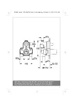
- Observe the installation depth in accordance with the 

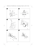
instructions given on the mounting template, see Fig. [1].
x = Face of tiles
y = Front face of mounting template
z = Resting point for spirit level

- Align the mixer horizontally, vertically and parallel to the wall, see 

Fig. [2] (place a spirit level on the cams or face of the mounting 
template).

- Install concealed thermostat mixer module in wall and connect 

pipelines, see Fig. [3]. The housing is provided with pre-drilled 
holes (A) to facilitate mounting the fitting to the wall, see Fig. [2].

Do not solder the connections between the pipelines and 

housing, otherwise the built-in non-return valves may be 
damaged.

- Seal the bottom outlet with screw plug.

Note

!

The hot water supply must be connected on the left (marked 

W (H) on housing) and the cold water supply on the right 
(marked K (C) on housing), as viewed from the operating posi-
tion.

Caution!

The upper outlets are sealed by the factory.

Checking pipes and thermostatic mixer body for leaks.

1. Remove screws (B) and fitting template (C),

see Fig. [5].

2. Install special socket spanner supplied (D) on shut-off    

spindle (E), see Fig. [4].

3. Turn spanner (D) clockwise and pressure test the bath outlet.

4. Turn spanner (D) anticlockwise and pressure test the shower 

outlet.

5. Return spanner (D) to starting position (fitting closed) and 

remove.

6. Reinstall fitting template (C).

Flush pipelines thoroughly.

1. Remove screws (B) and fitting template (C),

see Fig. [5].

2. Close the hot and cold water supplies.

3. Remove non-return valves (G), see Fig. [5].

4. Install flushing plugs (H) in non-return valve seat recesses, 

see Fig. [6].

5. Open the hot and cold water supplies and flush pipes 

thoroughly.

6. Close the hot and cold water supplies, remove flushing 

plugs (H) and reinstall non-return valves (G).

7. Open the hot and cold water supplies.

8. Install special socket spanner supplied (D) on shut-off    

spindle (E), see Fig. [4].

9. Turn spanner (D) clockwise and flush the bath outlet 

thoroughly.

  10. Turn spanner (D) anticlockwise and flush the shower outlet 

thoroughly.

  11. Return spanner (D) to starting position (fitting closed) and 

remove.

  12. Reinstall fitting template (C).

Plaster and tile the wall.

Do not remove the fitting template before final installation.

I954841.book : I95484GB.FM  Seite 2  Mittwoch, Februar 24, 1999  11:09 AM

Summary of Contents for 34 964

Page 1: ...CZ I FIN H Page 2 Page 3 Página 4 Pagina 5 Pagina 6 Side 8 Side 9 Sivu 10 Strona 11 Σελιδα 13 Strana 14 Oldal 15 P Página 16 Sayfa 17 TR RUS SK Strana 19 34 964 95 484 131 ÄM 30 134 02 99 954841 book T95484 FM Seite 1 Donnerstag Februar 25 1999 9 59 AM ...

Page 2: ...etterie Bitte diese Anleitung an den Benutzer der Armatur weitergeben Please pass these instructions on to the end user of the fitting S v p remettre cette instruction à l utilisateur de la robinetterie Bitte diese Anleitung an den Benutzer der Armatur weitergeben 954841 book T95484 FM Seite 2 Donnerstag Februar 25 1999 9 59 AM ...

Page 3: ...II 1 x y z 2 A A 3 E D 4 5 G C B H 6 954841 book T95484 FM Seite 3 Donnerstag Februar 25 1999 9 59 AM ...

Page 4: ...e Wand einbauen und an die Rohrleitungen anschließen s Abb 3 Zur einfacheren Befestigung der Armatur an der Wand sind am Gehäuse Befestigungslöcher A vorgesehen s Abb 2 Eine Lötverbindung zwischen Rohrleitungen und Gehäuse darf nicht vorgenommen werden da die eingebauten Rückflußverhinderer beschädigt werden können Den freibleibenden Abgang mit Gewindestopfen abdichten Wichtig Der Warmwasseranschl...

Page 5: ... 2 place a spirit level on the cams or face of the mounting template Install concealed thermostat mixer module in wall and connect pipelines see Fig 3 The housing is provided with pre drilled holes A to facilitate mounting the fitting to the wall see Fig 2 Do not solder the connections between the pipelines and housing otherwise the built in non return valves may be damaged Seal the bottom outlet ...

Page 6: ...encastrement Installer l appareil dans le mur et raccorder aux tuyauteries voir fig 3 Pour faciliter la fixation de la robinetterie au mur on a prévu des trous de fixation A sur le boîtier voir fig 2 Il n est pas permis de procéder à une jonction par brasage des tuyauteries et du boîtier car les clapets anti retour pourraient être endommagés Etanchéifier la sortie restée libre avec des bouchons fi...

Page 7: ...ctarla a las tuberías véase la fig 3 Para simplificar aún más la sujeción de la batería a la pared están previstos en la carcasa los orificios de sujeción A véase la fig 2 Las tuberías y la carcasa no deberán ser conectadas por soldadura pues podrían resultar dañadas las válvulas antirretorno Cerrar herméticamente con tapón roscado la salida que queda libre Importante La acometida del agua calient...

Page 8: ...ncasso e collegarlo ai tubi vedi fig 3 Per facilitare il fissaggio del rubinetto sulla parete nella scatola sono previsti fori appositi A vedi fig 2 Non effettuare saldature fra la scatola del termostato e i tubi perchè si potrebbe danneggiare la valvola di non ritorno incorporata Chiudere con tappo a vite il raccordo libero Importante Il raccordo dell acqua calda deve trovarsi a sinistra segno W ...

Page 9: ...en aan Zie fig 3 Om de kraan nog makkelijker tegen de wand te bevestigen werden op het kraanhuis bevestigingsgaten A voorgeboord Zie fig 2 Een soldeerverbinding tussen buisleidingen en kraanhuis is niet toegelaten omdat dit de ingebouwde terugslagkleppen kan beschadigen De niet gebruikte aansluitopening dicht u met schroefdraadstop af Belangrijk De warmwaterleiding moet u links markering W H op he...

Page 10: ...termostaten i väggen och anslut rörledningarna se fig 3 För att underlätta monteringen av armaturen på väggen har armaturhuset försetts med hål A se fig 2 Skarven mellan rörledningar och armaturhus får ej lödas eftersom de inbyggda backventilerna annars kan skadas Slut de fria utloppet med skruvpropp OBS Varmvattnet ska anslutas till vänster markering W H på huset och kallvattnet till höger marker...

Page 11: ...ingselementet indbygges i væggen og tilsluttes til rørledningerne se ill 3 For lettere at kunne fastgøre armaturet på væggen er der anbragt fastgørelses huller A på huset se ill 2 Der må ikke foretages nogen loddesamling mellem rørledningerne og huset da de indbyggede kontraventiler kunne blive beskadiget De afgang som forbliver fri tætnes med gevindprop Vigtigt Varmvandstilslutningen skal være ti...

Page 12: ...en monteres så i veggen og koples til rørledningene se ill 3 For å gjøre det enda enklere å feste armaturen på veggen er det laget monteringshull A på huset se ill 2 En loddforbindelse mellom rørledninger og hus må ikke utføres fordi de innebygde tilbakeslagsventilene kan skades De frie avgangene tettes med gjengeplugge Viktig Varmtvannskoplingen må utføres på venstre side markering W H på huset o...

Page 13: ... Asenna piiloasennus termostaatin asennusosa seinään ja liitä se vesijohtoihin ks kuva 3 Jotta laitteen kiinnitys seinään olisi yksinkertaisempaa on suojuksessa kiinnitysreikiä A ks kuva 2 Vesijohtoja ja suojusta ei saa juottaa toisiinsa kiinni koska sisäänasennetut takaiskuventtiilit voisivat vahingoittua Tiivistä vielä vapaana olevat vedenottokohdat kierretulpilla Tärkeää Lämpimän veden liitäntä...

Page 14: ...oziomicę położyć na krzywce lub na przedniej stronie szablonu montażowego Korpus termostatowy do zabudowy podtynkowej należy zabudować w ścianie i połączyć z przewodami rurowymi patrz rys 3 Dla ułatwienia zamocowania armatury na ścianie w obudowie zostały wykonane otwory mocujące A patrz rys 2 Nie należy stosować połączenia lutowanego pomiędzy przewodami rurowymi a korpusem bowiem może to doprowad...

Page 15: ...12 UAE I954841 book I95484UA FM Seite 12 Mittwoch Februar 24 1999 11 09 AM ...

Page 16: ...t µ w ª w w t q t q EDU º º q º µ º ª q º ª º º º q y º µ t q t ª ª 83 µ º µ l º º y m º º µ º º ª µ º º º º t ª º ª º q º ª º º º µ µ µ ª º t t º º t p º µ ª p µ ª µ ª y º ª µ ª y º t t º º t µ º I954841 book I95484GR FM Seite 13 Mittwoch Februar 24 1999 11 09 AM ...

Page 17: ...anu montá ní šablony Zabudujte montá ní těleso zapuštěného termostatu do stěny a napojte na potrubí viz zobr 3 Pro snadné upevnění armatury na stěnu jsou připravené upevňovací otvory A na krytu viz zobr 2 Mezi potrubím a krytem se nesmí provést spojení pájením nebo by mohly být poškozeny zabudované zpětné klapky Utěsněte zbývající odtoky závitovou zátkou Důle ité Napojení teplé vody se musí provés...

Page 18: ...séget helyezzük a falba majd csatlakoztassuk a csővezetékekhez ld a 3 ábrát A csaptelep falra rögzítésének megkönnyítésére annak burkolatán rögzítőlyukak A találhatók ld a 2 ábrát a csővezetékek és a csaptelep burkolata között nem szabad forrasztani mivel a beépített visszafolyásgátlók megsérülhetnek a csatlakozás nélkül maradt csőcsonkokat menetes dugasszal tömítsük le Fontos a melegvíz csatlakoz...

Page 19: ...al e paralelo à parede ver fig 2 apoie o nível sobre o excêntrico ou sobre a parte frontal da matriz de montagem Monte o corpo de montagem do termóstato UP na parede e faça as ligações das canalizações ver fig 3 Para uma fixação mais simples da estrutura à parede há furos de fixação A na caixa ver fig 2 Não deve ser feita uma ligação por soldadura entre os canos e a caixa uma vez que os dispositiv...

Page 20: ...GÞmme termostatik bataryayå duvara monte edin ve boru baØlantålarånå yapån UP Termostatån iÏerisindeki takålå parÏalarå duvara takån ve borulara baØlayån bkz æekil 3 Armatärä duvara kolay bir æekilde sabitlemek iÏin gÞvdede sabitleme delikleri A bulunmaktadår bkz æekil 2 Cek valfleri hasar gÞrebileceØi iÏin borular ile gÞvde arasånda lehim yapålmamalådår Boæ kalan Ïåkåælarån kÞr tapa ile kapatålma...

Page 21: ... ÇÈ ÃÀ ÇÂ Æ Ç ÉÆÄ ÃÒ ÉÀÁ ºÑ ÈÒ Ã ÑÇÈÉÅÑ Á Ã Å Æ ºÃÔÔ ÇÈÄÆÄÃÉ ÂÄÃÈ ÃÄ Ä Î ÁÄà lÄÆÅÉÇ ÇÂ Ç È Áµ È ÆÂÄÇÈ È ºÁµ ÇÈÆÄ ÃÃÄ Ä ÂÄÃÈ ÇÈÆÄ ÈÒ ÇÈ ÃÉ ÅÆ ÇÄ º à ÈÒ À ÈÆÉ ÄÅÆÄ Äº  ÇÂ Æ Ç fÁµ ÉÅÆÄÏ Ã µ ÀÆ ÅÁ à µ Æ ÈÉÆÑ À ÇÈ Ã Ã ÀÄÆÅÉÇ ÅÆ ºÉÇÂÄÈÆ ÃÑ ÄÈ ÆÇÈ µ b ÇÂ Æ Ç o ºÄÅÉÇÀ Èǵ ÇÄ º õÈÒ ÀÄÆÅÉÇ Ç ÈÆÉ ÄÅÆÄ Äº  ŠÀÄ È À À À ÓÈÄ ÂÄ È Ñ ÈÒ ÅÄ Æ º à ÇÈÆÄ ÃÃÑË Ä Æ ÈÃÑË ÀÁ Å ÃÄ s Ä ÄºÃÑ Ñ ÄºÑ ÇÁ ºÉ È ÀÆÑÈÒ Æ Ò Ä ÑÂ...

Page 22: ...polo i na zará ky poprípade na prednú stranu montá nej šablóny Zabudova do steny montá ne teleso podomietkového termostatu UP a pripoji na rúrky pozri obr 3 Pre jednoduchšie upevnenie armatúry na stenu sú predurčené otovry v telese A pozri obr 2 Pájkované spoje potrubia s telesom sú neprípustné preto e zabudované mô u by poškodené zabudované zamedzovače spätného toku Utesni vo4né vývody závitovými...

Page 23: ...954841 book NOTIZEN1 FM Seite 21 Donnerstag Februar 25 1999 9 59 AM ...

Page 24: ...954841 book NOTIZEN2 FM Seite 22 Donnerstag Februar 25 1999 9 59 AM ...

Page 25: ...954841 book NOTIZEN FM Seite 20 Donnerstag Februar 25 1999 9 59 AM ...

Page 26: ...954841 book ADRESNEU FM Seite 23 Donnerstag Februar 25 1999 9 59 AM ...

Reviews: