Grizzly T23108 Owner'S Manual Download Page 29

Model T23108 (Mfg. Since 7/10)

-27-

15.  Rotate  the  clamp  lever  to  the  right  to  firmly 

secure the chain between the clamp plates of 
the chain holder.

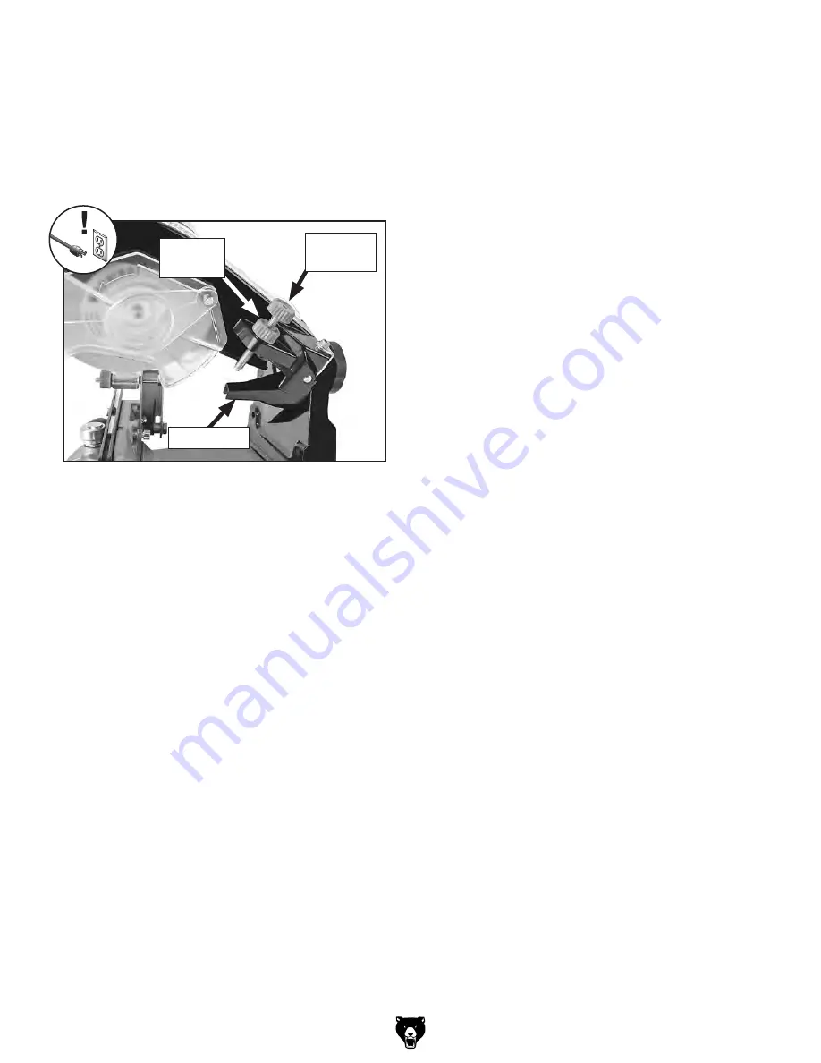
16.  Lower the grinding wheel into the cutter gullet 

until it stops, then thread the depth knob bolt 
down  until  it  is  against  the  depth  stop  (see 

Figure 33).


Important:  When adjusting the depth knob 
bolt, keep in mind that you want to replace 
and sharpen angles that may be worn or 
damaged. Do not make the gullet any deeper 
than is necessary to accomplish this.


Also, taking deep cuts with the grinding wheel 
could burn the metal, which will damage 
the temper of the steel. Chain cutters that 
are heated excessively during sharpening 
become brittle and dull quickly. 


It is better to make a few light passes than  
one deep one!

17.  Back the depth knob bolt away from the depth 

stop by a small amount, then thread the knob 
lock nut down to secure the setting.

18.  Adjust  the  advancement  guide  so  that  the 

chain  moves  slightly  to  the  right.  This  will 
remove a small amount from the top and side 
plates and provide the sharpened angles.


Note:  This critical adjustment is a matter of 
trial-and-error and experience.

19.  Connect the sharpener to power and wait for 

the wheel to come to full speed.

20.  Using  a  slow  and  steady  pace,  lower  the 

grinding wheel into the first cutter link until the 
depth  bolt  hits  against  the  depth  stop,  then 
allow  the  spring-loaded  swing  arm  to  raise 
the grinding wheel slowly.

21.  While taking care not to contact the spinning 

grinding wheel with your hands or the chain, 
rotate  the  clamp  lever  to  the  left  enough  to 
release the chain from the clamp plates.

22.  Slowly  pull  the  chain  to  the  right  until  the 

advancement  guide  falls  behind  the  next 
cutter link for that side, then

 pull the chain to 

the left to firmly seat the advancement guide 
against the rear of the cutter link to be sharp-
ened.  This  will  properly  position  the  link  for 
sharpening.

23.  Re-tighten the clamp lever and repeat Steps 

19–22  until  all  cutters  for  that  side  of  the 
chain have been sharpened.

24.  Turn  the  sharpener  OFF  and  wait  for  the 

grinding  wheel  to  completely  stop,  then  dis-
connect the sharpener from power.

25.  Release the chain from the clamp plates, turn 

it around 180° so that the cutters on the other 
side of the chain are ready for sharpening.

26.  Rotate the chain holder to align with the angle 

marks on the other side of the rotation scale, 
and,  if  the  chain  requires  a  gullet  angle,  tilt 
the  chain  holder  10°  in  the  opposite  direc-
tion.

27.  When  you  are  satisfied  that  the  sharpener 

settings  are  correct,  repeat 

Steps 18–23 

for the rest of the cutters on that side of the 
chain.

28.  Check, and if necessary, adjust the height of 

the depth gauges. Refer to the next subsec-
tion for more information.

29.  Clean and lubricate the chain per the manu-

facturer's  recommendation  before  re-install-
ing it onto the chain saw.

Figure 33. Depth stop and controls.

Depth

Knob Bolt

Knob

Lock Nut

Depth Stop

Summary of Contents for T23108

Page 1: ...IGHT OCTOBER 2010 BY GRIZZLY INDUSTRIAL INC REVISED JANUARY 2015 TR WARNING NO PORTION OF THIS MANUAL MAY BE REPRODUCED IN ANY SHAPE OR FORM WITHOUT THE WRITTEN APPROVAL OF GRIZZLY INDUSTRIAL INC FOR MODELS MANUFACTURED SINCE 7 10 TS13269 PRINTED IN CHINA ...

Page 2: ...ng grinding tool integrity and the usage of personal protective equipment The manufacturer will not be held liable for injury or property damage from negligence improper training machine modifications or misuse Some dust created by power sanding sawing grinding drilling and other construction activities contains chemicals known to the State of California to cause cancer birth defects or other repr...

Page 3: ...ite Considerations 11 Mounting 12 Assembly 13 Installing Grinding Wheel 14 Power Connection 15 Test Run 15 SECTION 4 OPERATIONS Chain Saw Terminology 16 How the Chain Cuts 19 Grinding Wheel Selection 20 Wheel Inspection Ring Test 21 Top Plate Angle 22 Top Plate Cutting Angle 23 Gullet Angle 24 Sharpening Operation 25 Depth Gauge Setting 28 Clamp Plate Adjustment 28 SECTION 5 MAINTENANCE Schedule 2...

Page 4: ... will be slightly different than what is shown in the manual If you find this to be the case and the difference between the manual and machine leaves you confused about a procedure check our website for an updated version We post current manuals and manual updates for free on our website at www grizzly com Alternatively you can call our Technical Support for help Before calling please write down t...

Page 5: ...hine read and understand this entire manual before beginning any operations Figure 1 Model T23108 identification Swing Arm Assembly Motor Swing Arm Handle Wheel Arbor Guards Chain Clamp Lever Swing Arm Lock Knob ON OFF Switch Chain Holder Assembly Chain Holder Lock Knob Base Depth Lock Bolt Depth Stop ...

Page 6: ...oof DANGEROUS ENVIRONMENTS Do not use machinery in areas that are wet cluttered or have poor lighting Operating machinery in these areas greatly increases the risk of accidents and injury MENTAL ALERTNESS REQUIRED Full mental alertness is required for safe operation of machin ery Never operate under the influence of drugs or alcohol when tired or when distracted For Your Own Safety Read Instructio...

Page 7: ...educe accidental contact with moving parts or flying debris Make sure they are properly installed undamaged and working correctly FORCING MACHINERY Do not force machine It will do the job safer and better at the rate for which it was designed NEVER STAND ON MACHINE Serious injury may occur if machine is tipped or if the cutting tool is unintentionally contacted STABLE MACHINE Unexpected movement d...

Page 8: ...er sonal injury damage to equipment or poor work results Like all machinery there is potential danger when operating this machine Accidents are frequently caused by lack of familiarity or failure to pay attention Use this machine with respect and caution to decrease the risk of operator injury If normal safety pre cautions are overlooked or ignored serious personal injury may occur TOP PLATE LENGT...

Page 9: ... for a sufficient length of time damage overheating or fire may result especially if connected to an undersized circuit To reduce the risk of these hazards avoid over loading the machine during operation and make sure it is connected to a power supply circuit that meets the specified circuit requirements For your own safety and protection of property consult an electrician if you are unsure about ...

Page 10: ... extension cord size gets longer and the gauge size gets smaller higher gauge numbers indicate smaller sizes Any extension cord used with this machine must be in good condition and contain a ground wire and matching plug receptacle Additionally it must meet the following size requirements Minimum Gauge Size 14 AWG Maximum Length Shorter is Better 50 ft Grounding Plug Requirements This machine is e...

Page 11: ...eded for Setup Your machine was carefully packaged for safe transportation Remove the packaging materials from around your machine and inspect it If you discover the machine is damaged please imme diately call Customer Service at 570 546 9663 for advice Save the containers and all packing materials for possible inspection by the carrier or its agent Otherwise filing a freight claim can be difficul...

Page 12: ...n this list care fully check around inside the machine and packaging materials Often these items get lost in packaging materials while unpack ing or they are pre installed at the factory Inventory Figure 3 Qty A Swing Arm Handle 1 B Combo Wrench 8mm 1 C Base Chain Holder Assembly 1 D Hex Wrench 4 5mm 1 Each E Chain Gauge 1 F Wheel Dressing Block 1 G Motor Swing Arm w Wheel 1 4 Thick 1 H Fender Was...

Page 13: ... The physical environment where your machine is operated is important for safe operation and the longevity of its components For best results operate this machine in a dry environment that is free from excessive moisture hazardous chemi cals airborne abrasives or extreme conditions Extreme conditions for this type of machinery are generally those where the ambient temperature range exceeds 41 104 ...

Page 14: ...Hex Nut Figure 6 Example of a through mount setup Machine Base Workbench Lag Screw Flat Washer Figure 7 Example of a direct mount setup Another option for mounting is a Direct Mount where the machine is simply secured to the work bench with a lag screw and flat washer The strongest mounting option is a Through Mount where holes are drilled all the way through the workbench then hex bolts washers a...

Page 15: ...olding the swing arm in place insert the M10 1 5 x 40 hex bolt through the hex shaped hole in the swing arm vertical face then secure the arm to the base with the 10mm fender washer and M10 1 5 lock knob as shown in Figures 9 10 4 Thread the handle onto the end of the swing arm as shown in Figure 11 Figure 8 Swing arm pivot stud and matching hole Pivot Stud Hole Base Vertical Face Figure 9 Swing a...

Page 16: ...the grinding wheel on the inner flange 7 Replace the outer flange and arbor cap screw then tighten the cap screw to approxi mately 60 inch pounds Over tightening the arbor cap screw could cause the grinding wheel to crack and break apart during operation which would send flying debris at the operator DO NOT over tighten the arbor cap screw If possible use a torque wrench to ensure that the cap scr...

Page 17: ...machine should run smoothly with little or no vibration or rubbing noises Strange or unusual noises should be inves tigated and corrected before operating the machine further Always disconnect the machine from power when investigating or correcting potential problems 5 Turn the machine OFF push the O but ton Power Connection Before the machine can be connected to the power source an electrical cir...

Page 18: ...ng this machine read and understand this entire manual before beginning any operations Damage to your eyes lungs and hands could result from using this machine without proper protective gear Always wear safety glasses a respirator and leather gloves when operating this machine Chain Saw Terminology Refer to the following descriptions and illustrations to better understand the chain saw terminology...

Page 19: ...e a number 7 and is comprised of the top plate and side plate see Figure 17 The rake that the top plate angles back from the side plate is called the top plate angle and is generally 25 35 This makes a sharp point that begins the cut Top Plate Cutting Angle Top View Side View Top Plate Angle Front View Figure 17 Cutter link top plate angle and cutting angle Top Plate Cutting Angle The top plate cu...

Page 20: ...s remember to check and if necessary adjust the depth gauge setting Depth Gauge Setting Clearance Angle Depth Gauge Figure 19 Clearance angle and depth gauge setting Clearance Angle The clearance angle see Figure 19 is the amount that the top plate angles down from the leading edge to the rear of the cut ter link This clearance angle allows the cutter link to pivot up into the wood and then down a...

Page 21: ...ions for the cutter specifications when sharpen ing the chain 1 Chain Travel 2 3 4 5 Figure 21 The rocking self feeding motion of the cutter link during a cutting operation As illustrated in Figure 21 below when the cutting point at the top of the cutter moves against the wood 1 the front of the cutter pivots up until the depth gauge meets the wood 2 which forces the cutter to pivot even farther i...

Page 22: ...0 10 0 025 3 8 0 050 1 8 25 60 10 0 025 3 8 0 058 1 8 25 60 10 0 025 3 8 0 063 1 8 25 60 10 0 025 0 404 0 058 3 16 25 60 10 0 025 0 404 0 063 3 16 25 60 10 0 025 0 404 0 080 3 16 35 60 10 0 050 3 4 0 122 1 4 35 60 10 0 070 1 2 1 2 1 2 1 2 1 2 Figure 22 Typical chain saw sharpening specifications Grinding wheels that break apart during operation can send high speed debris at the operator or bystand...

Page 23: ...heel does not pass the ring test DO NOT use the wheel To perform a ring test 1 Make sure the wheel that you test is clean and dry otherwise you may get false results 2 If size permits balance the wheel with your finger in the center hole If this is not possible hang the wheel in the air with a piece of cord or string looped through the bore Figure 23 Tapping locations for a ring test 4 An undamage...

Page 24: ... Loosen the chain holder lock knob 3 Rotate the chain holder to align the mark on the chain holder base with the angle mark on that scale that is right for your chain then re tighten the lock knob Tip The chain holder is easier to rotate if the holder tilt is at 0 see Gullet Angle on Page 24 for detailed instructions When setting up the sharpener the top plate angle is determined by the rotational...

Page 25: ...ays refer to the chain manufacturer s specifications when setting up the sharpener However if this information is not available use the chart in Figure 22 on Page 20 as a general guide To set the grinding wheel tilt for the top plate cutting angle 1 DISCONNECT MACHINE FROM POWER 2 Loosen the swing arm lock knob see Figure 27 3 Reference the angle scale on top of the base vertical face to adjust th...

Page 26: ...e properly aligned 5 To bring the chain holder back to 0 align the casting center tilt mark with the base mark The gullet angle is determined by the tilt of the chain holder The chain holder can be tilted to 0 or 10 in and out Note Always refer to the chain manufacturer s specifications when setting up the sharpener However if this information is not available use the chart in Figure 22 on Page 20...

Page 27: ...aking apart during cutting opera tion If you suspect that any cutter top plate will be shorter than 1 4 in length after being sharpened replace that link or replace the chain 4 DISCONNECT MACHINE FROM POWER 5 Read and understand all the safety instruc tions listed in the beginning of this manual and included with the chain saw owner s manual 6 Make sure the sharpener is firmly secured to the workb...

Page 28: ...utter to be sharpened then pull the chain to the left until the guide catches and stops the chain see Figure 32 11 Use the clamp lever see Figure 31 to set the gap between the clamp plates to match the chain gauge which will allow the chain to easily move along the top of the clamping bars in the same manner it moves along the chain saw bar 12 Locate the cutter link with the shortest top plate len...

Page 29: ...n allow the spring loaded swing arm to raise the grinding wheel slowly 21 While taking care not to contact the spinning grinding wheel with your hands or the chain rotate the clamp lever to the left enough to release the chain from the clamp plates 22 Slowly pull the chain to the right until the advancement guide falls behind the next cutter link for that side then pull the chain to the left to fi...

Page 30: ...s setting is critical to the efficient operation of the chain saw No matter how well the chain is sharpened if the depth gauge setting is not properly main tained the chain will not be able to efficiently cut the wood We strongly recommend that you research the many methods and tools for maintaining the prop er depth gauge setting for your chain and choose the best solution that works for you Clam...

Page 31: ...on unless they need replacement Dressing Wheels The edge profile and surface condition of the grinding wheel see Figure 36 is critical in main taining the proper shape of the top plate side plate and gullet when sharpening Grinding Wheel Edge Profile Correct Worn Figure 36 Grinding wheel edge profile With use the abrasive surface of the grinding wheel becomes embedded with material from the chain ...

Page 32: ...e sharpener settings are correct for the chain 5 Clean motor let cool and reduce workload 6 Test repair replace Machine has vibration or noisy operation 1 Motor or component loose 2 Grinding wheel at fault arbor hole not round 3 Incorrectly mounted to workbench 4 Motor fan rubbing on fan cover 5 Motor bearings at fault 6 Motor shaft bent 1 Inspect replace damaged bolts nuts and re tighten with thr...

Page 33: ...eck all wires dis connected or connected during any wiring task to ensure tight connections CIRCUIT REQUIREMENTS You MUST follow the requirements at the beginning of this manual when connecting your machine to a power source WIRE COMPONENT DAMAGE Damaged wires or components increase the risk of serious per sonal injury fire or machine damage If you notice that any wires or components are damaged w...

Page 34: ... Since 7 10 READ ELECTRICAL SAFETY ON PAGE 31 T23108 Wiring Diagram Gnd Light ON OFF Switch 110V Motor Neutral Hot Ground 110VAC NEMA 5 15 Plug As Recommended Start Capacitor 12MFD 250VAC IN OUT L N Figure 37 T23108 wiring ...

Page 35: ...own Diagram 1 2 3 4 5 6 7 8 9 10 11 13 14 15 16 17 18 20 21 24 25 29 30 31 32 33 34 35 36 37 38 39 46 46 47 49 51 52 54 56 58 60 61 62 63 64 65 66 67 68 69 71 14 46 21 47 53 40 53 53 53 49 49 32 36 55 19 22 23 26 27 28 42 43 44 45 50 57 59 72 73 16 1 16 2 ...

Page 36: ...FAN COVER 53 PN01M HEX NUT M6 1 16 2 PT23108016 2 MOTOR FAN 54 PN32M HEX NUT M14 2 17 PT23108017 SWING ARM PIVOT BRACKET 55 PN03M HEX NUT M8 1 25 18 PT23108018 PIVOT AXLE 56 PW01M FLAT WASHER 8MM 19 PT23108019 KNOB M10 1 5 57 PWF10M FENDER WASHER 10MM 20 PT23108020 TORSION SPRING 58 PT23108058 THIN HEX NUT M14 2 21 PT23108021 BUSHING 59 PSTB004M STEEL BALL 5MM 22 PT23108022 BASE 60 PT23108060 WHEE...

Page 37: ... metalworker ____ 0 2 Years ____ 2 8 Years ____ 8 20 Years ____20 Years 6 How many of your machines or tools are Grizzly ____ 0 2 ____ 3 5 ____ 6 9 ____10 7 Do you think your machine represents a good value _____Yes _____No 8 Would you recommend Grizzly Industrial to a friend _____Yes _____No 9 Would you allow us to use your name as a reference for Grizzly customers in your area Note We never use ...

Page 38: ...D LINE FOLD ALONG DOTTED LINE GRIZZLY INDUSTRIAL INC P O BOX 2069 BELLINGHAM WA 98227 2069 Place Stamp Here Name_______________________________ Street_______________________________ City______________State______Zip______ Send a Grizzly Catalog to a friend ...

Page 39: ...e tried in the State of Washington County of Whatcom We shall in no event be liable for death injuries to persons or property or for incidental contingent special or consequential damages arising from the use of our products To take advantage of this warranty contact us by mail or phone and give us all the details We will then issue you a Return Number which must be clearly posted on the outside a...

Page 40: ......

Reviews: