background image

Model g0634Xp (Mfg. 4/11+)

-9-

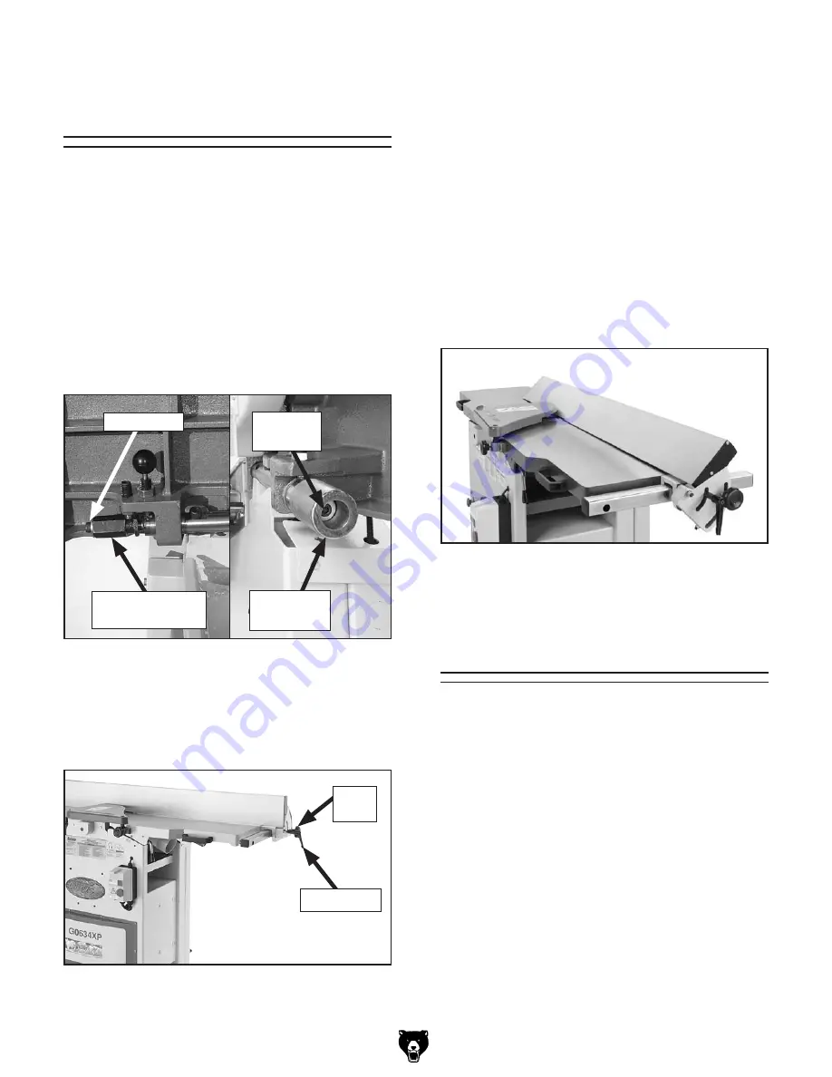
figure 6. Fence at 45° outward position.

to move the fence to 45° outward, loosen the tilt 
knob, move the fence 

 to the 45° outward position 

(see 

figure 6), then tighten the tilt knob. Verify the 

angle with a 45° square. to return the fence to the 
90° position, loosen the tilt knob, raise the fence 
to 90°, and tighten the tilt knob. Check the fence 
angle with a 90° square, and make sure the fence 
and table are flush.

basic Jointer 

controls

All basic controls used during routine jointer oper-
ations  on  the  g0634Xp  are  the  same  as  those 
described on 

pages 22–23 of the manual except 

for  "table  Movement,"  "Fence  Movement,"  and 
"Fence tilting."

fence  tilting:  the  tilt  knob  (figure  5)  secures 
the  fence  at  any  position  in  the  available  range. 
Fence stops set the fence at 90° or 45° outward. 
the  tilt  knob  must  be  tightened  before  jointing. 
see 

page  10  in  this  insert  for  more  detail  on 

adjusting the fence stops.

fence  movement:  the  fence  lock  lever  keeps 
the  fence  in  position  (see 

figure  5).  to  move 

the fence, loosen the lever, slide the fence in the 
desired direction, then tighten the lever.

figure 5. Fence lock location.

tilt 

Knob

lock lever

Jointer-planer 

conversion

Model g0634Xp jointer-planer operations are the 
same as those described on 

pages 24–25 of the 

manual, with the exception of 

step 3

to set up the machine for planer operations:

1.  disCoNNECt  JoiNtEr/plANEr  FroM 

poWEr soUrCE!

2.  remove the cutterhead guard. 

3.  loosen  the  fence  lock  lever  (figure  5)  and 

slide the fence off of the machine.  

4.  perform steps 4–9 in the manual.

table  movement:  Unlock  the  table  lock  levers, 
then loosen the cap screws on the infeed handgrip 
or outfeed table adjustment knob (see 

figure 4

before moving the infeed and outfeed tables. Use 
an  adjustable  wrench  to  turn  the  outfeed  adjust-
ment knob.

figure 4. table control locations.

outfeed table 

Adj. Knob

infeed 

handgrip

Cap screw

Cap 

screw

Summary of Contents for Polar Bear G0634XP

Page 1: ...ntire G0633 G0634 manual to reduce the risk of serious personal injury If you have any questions about this manual insert or the differences between the Model G0634XP and the Model G0633 G0634 contact...

Page 2: ...FT BRACKET LEFT 802 P0634XP802 MACHINE ID LABEL 2 P0634XP002 DRIVE SHAFT COVER 808 PPAINT 24 PB WHITE TOUCH UP PAINT 3 1 P0634XP003 1 COVER 810 P0634XP810 MODEL LABEL 4 P0634XP004 DOOR 811 PLABEL 75 P...

Page 3: ...CUTTERHD 12 10 32 V2 09 09 204 1A P0634XP204 1A PLANER DUST PORT 201 1 H9893 INDEXABLE CUTTER 15 X 15 X 2 5 215 P0634XP215 DUST CHUTE 201 2 PFH32 FLAT HEAD TORX 10 32 X 1 2 215 6 P0634XP215 6 BRACKET...

Page 4: ...634XP608 REAR GUARD CONNECTOR 627 PFH01 FLAT HD SCR 10 24 X 3 8 608 1 P0634XP608 1 REAR GUARD LINK 631V2 P0634XP631V2 FENCE RAIL W BRACE HOLES V2 04 11 609 P0634XP609 FENCE ANGLE SCALE 634 PLW04 LOCK...

Page 5: ...ZbZci K H c aZ E VhZ o B c bjb 8 gXj i H oZ 6be Hl iX BV cZi X l i I ZgbVa DkZgadVY EgdiZXi dc Hl iX KdaiV Z K 8dgY AZc i i 8dgY Vj Z Vj Z Eaj cXajYZY Cd GZXdbbZcZY Eaj IneZ C B6 A Motors Main IneZ I...

Page 6: ...n Planer IVWaZ AZc i c IVWaZ L Yi c IVWaZ I X cZhh c addg Id IVWaZ Z i c Construction 7dYn 6hhZbWan 8dchigjXi dc 8Vhi gdc 8jiiZg ZVY 6hhZbWan 8dchigjXi dc HiZZa c ZZY GdaaZg 8dchigjXi dc HiZZa Dji ZZY...

Page 7: ...XdccZXiZY id Vc jcYZgh oZY X gXj i Id gZYjXZ i Z g h d i ZhZ VoVgYh Vkd Y dkZg adVY c i Z bVX cZ Yjg c deZgVi dc VcY bV Z hjgZ i h XdccZXiZY id V edlZg hjeean X gXj i i Vi bZZih i Z gZfj gZbZcih c i Z...

Page 8: ...cdi XdccZXi i Z Zfj ebZci gdjcY c l gZ id V a kZ XjggZci XVggn c iZgb cVa 8 ZX l i V fjVa ZY ZaZXig X Vc dg hZgk XZ eZg hdccZa ndj Yd cdi jcYZghiVcY i ZhZ gdjcY c gZfj gZbZcih dg ndj VgZ c YdjWi VWdj...

Page 9: ...g See Page 10 in this insert for more detail on adjusting the fence stops Fence Movement The fence lock lever keeps the fence in position see Figure 5 To move the fence loosen the lever slide the fenc...

Page 10: ...and 90 Tools Needed Qty 45 Square 1 90 Square 1 Sliding Bevel 1 Wrench 10mm 1 Wrench 12mm 1 Hex Wrench 3mm 1 Hex Wrench 4mm 1 To set the 90 fence stop 1 Loosen the lock nut on the 90 fence stop screw...

Page 11: ...quipped with 32 indexable car bide inserts Each insert can be rotated to reveal any one of its four cutting edges Therefore if one cutting edge becomes dull or damaged simply rotate it 90 to reveal a...

Page 12: ...able marks on your workpieces the next time you plane 5 Lubricate the Torx screw threads with a light machine oil wipe the excess oil off the threads and torque the Torx screw to 55 inch pounds Note D...

Reviews: