background image

MODEL G0642

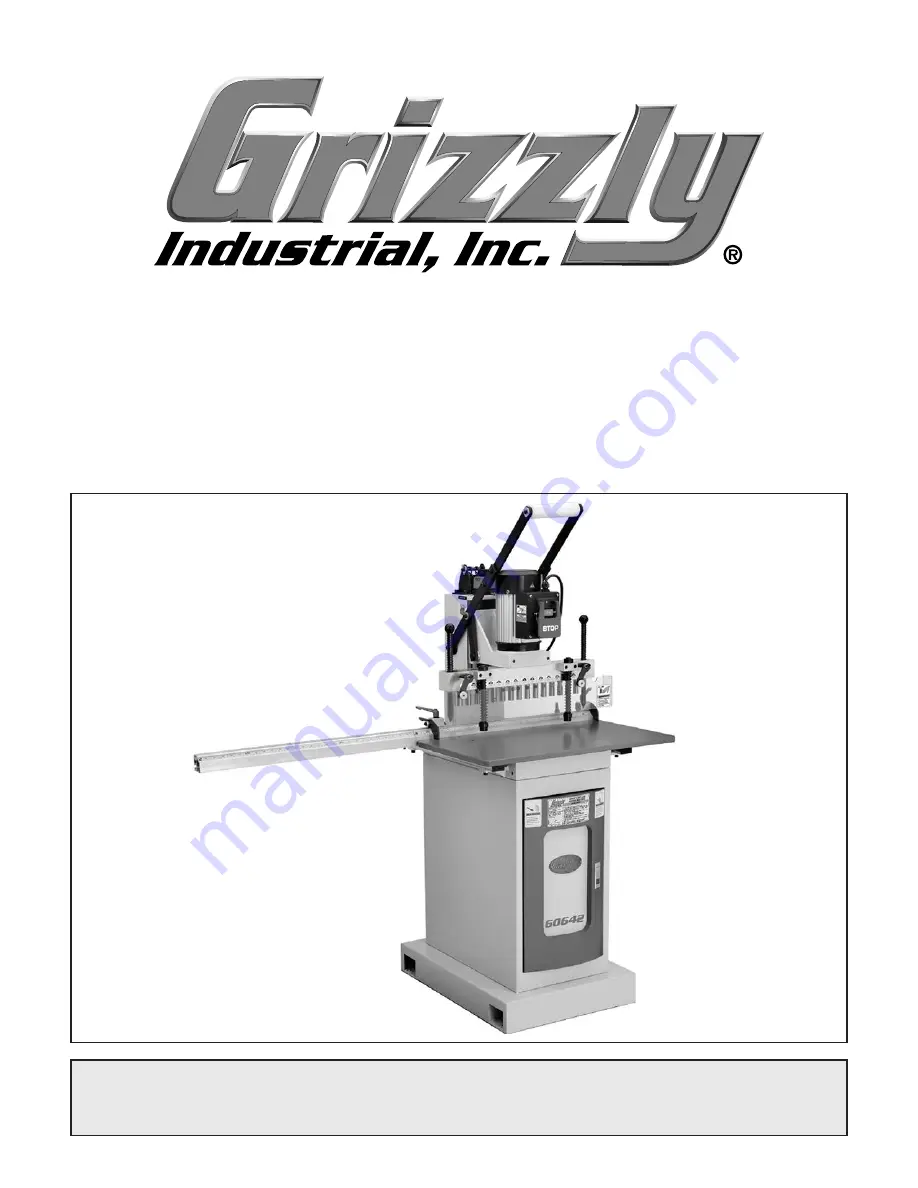
15-BIT LINE BORING MACHINE

OWNER'S MANUAL

(For models manufactured since 11/14)

COPYRIGHT © NOVEMBER, 2007 BY GRIZZLY INDUSTRIAL, INC., REVISED MARCH, 2018 (HE)

WARNING: NO PORTION OF THIS MANUAL MAY BE REPRODUCED IN ANY SHAPE

 OR FORM WITHOUT THE WRITTEN APPROVAL OF GRIZZLY INDUSTRIAL, INC.

#TS9904  PRINTED IN TAIWAN

V2.03.18

Summary of Contents for Line Boring Machine G0642

Page 1: ...els manufactured since 11 14 COPYRIGHT NOVEMBER 2007 BY GRIZZLY INDUSTRIAL INC REVISED MARCH 2018 HE WARNING NO PORTION OF THIS MANUAL MAY BE REPRODUCED IN ANY SHAPE OR FORM WITHOUT THE WRITTEN APPROVAL OF GRIZZLY INDUSTRIAL INC TS9904 PRINTED IN TAIWAN V2 03 18 ...

Page 2: ...ng grinding tool integrity and the usage of personal protective equipment The manufacturer will not be held liable for injury or property damage from negligence improper training machine modifications or misuse Some dust created by power sanding sawing grinding drilling and other construction activities contains chemicals known to the State of California to cause cancer birth defects or other repr...

Page 3: ...N 2 Manual Accuracy 2 Contact Info 2 Identification 3 Machine Data Sheet 4 SECTION 1 SAFETY 5 Safety Instructions for Machinery 5 Additional Safety for Line Boring Machines 7 SECTION 2 POWER SUPPLY 8 SECTION 3 SETUP 10 Setup Safety 10 Items Needed for Setup 10 Unpacking 10 Inventory 11 Clean Up 12 Site Considerations 13 Mounting to Shop Floor 14 Lifting Placing 15 Assembly 16 Test Run 17 SECTION 4...

Page 4: ...p Before calling make sure you write down the Manufacture Date and Serial Number from the machine ID label see below This information is required for us to provide proper tech support and it helps us determine if updated documenta tion is available for your machine Manufacture Date Serial Number Manual Accuracy We stand behind our machines If you have ques tions or need help contact us with the in...

Page 5: ...ng Head Assembly D Drilling Depth Control E Downfeed Handle F 1 HP Motor G ON OFF Switch Identification A H Indexing Pin I Boring Head Guard J Table K Cabinet Door L Cabinet Mounting Point M Workpiece Hold down N Cross Fence and Scale B D E F G H I J K L M N C To reduce your risk of serious injury read this entire manual BEFORE using machine ...

Page 6: ...ositions the workpiece for additional drilling beyond 15 holes I Throat Adjustment Knob Adjusts the bor ing head bit position laterally J Table Fence and Scale The fence sup ports the workpiece during the boring opera tion The fence scale is used to position the workpiece relative to the boring bits A G C F E I H Figure 2 Model G0642 basic controls J B D No list of safety guidelines can be complet...

Page 7: ...st Ship Upright Yes Electrical Power Requirement 110V or 220V Single Phase 60 Hz Prewired Voltage 110V Full Load Current Rating 10A at 110V 5A at 220V Minimum Circuit Size 15A at 110V 15A at 220V Connection Type Cord Plug Power Cord Included Yes Power Cord Length 9 1 2 ft Power Cord Gauge 14 AWG Plug Included Yes Included Plug Type 5 15 Switch Type ON OFF Push Button Switch w Large Shut Off Paddle...

Page 8: ... proof DANGEROUS ENVIRONMENTS Do not use machinery in areas that are wet cluttered or have poor lighting Operating machinery in these areas greatly increases the risk of accidents and injury MENTAL ALERTNESS REQUIRED Full mental alertness is required for safe operation of machin ery Never operate under the influence of drugs or alcohol when tired or when distracted For Your Own Safety Read Instruc...

Page 9: ... moving parts or flying debris Make sure they are properly installed undamaged and working correctly BEFORE operating machine FORCING MACHINERY Do not force machine It will do the job safer and better at the rate for which it was designed NEVER STAND ON MACHINE Serious injury may occur if machine is tipped or if the cutting tool is unintentionally contacted STABLE MACHINE Unexpected movement dur i...

Page 10: ...it never clear chips while spindle is turning To avoid cuts and eye injuries DO NOT clear chips by hand or with compressed air use a brush or vacuum instead DISCONNECT POWER FIRST To reduce risk of electrocution or injury from unexpected startup make sure drill is turned OFF disconnected from power and all moving parts have come to a complete stop before changing bits cutting tools or starting any...

Page 11: ...and make sure it is connected to a power supply circuit that meets the specified circuit requirements For your own safety and protection of property consult an electrician if you are unsure about wiring practices or electrical codes in your area Note Circuit requirements in this manual apply to a dedicated circuit where only one machine will be running on the circuit at a time If machine will be c...

Page 12: ...llowing size requirements Minimum Gauge Size 12 AWG Maximum Length Shorter is Better 50 ft Grounding Requirements This machine MUST be grounded In the event of certain malfunctions or breakdowns grounding reduces the risk of electric shock by providing a path of least resistance for electric current Figure 3 Typical 5 15 plug and receptacle Grounding Prong Neutral Hot 5 15 PLUG GROUNDED 5 15 RECEP...

Page 13: ...otor Wired for 110V Pre Wired Start Capacitor 300MFD 125VAC Run Capacitor 50MFD 250VAC O N S T O P Ground 110V Bk Wt Gn 4 2 3 1 4 2 3 1 Motor Wired for 220V Start Capacitor 300MFD 125VAC Run Capacitor 50MFD 250VAC O N S T O P Ground 220V Bk Wt Gn 4 2 3 1 4 2 3 1 N B Wt G NEM H H Gr 2 Bk Wt Gn NEM As Re Switch Switch Rd Rd Rd Rd Rd Rd Rd Rd Loosen These Screws 4 Loosen the screws indicated in Figur...

Page 14: ...arate all enclosed items from packaging materials and inspect them for shipping damage If items are damaged please call us immediately at 570 546 9663 IMPORTANT Save all packaging materials until you are completely satisfied with the machine and have resolved any issues between Grizzly or the shipping agent You MUST have the original pack aging to file a freight claim It is also extremely helpful ...

Page 15: ... D E B The following is a list of items shipped with your machine Before beginning setup lay these items out and inventory them If any non proprietary parts are missing e g a nut or a washer we will gladly replace them or for the sake of expediency replacements can be obtained at your local hardware store NOTICE If you cannot find an item on this list care fully check around inside the machine and...

Page 16: ... 14 Model G0642 Mfd Since 11 14 Hardware Recognition Chart USE THIS CHART TO MATCH UP HARDWARE DURING THE INVENTORY AND ASSEMBLY PROCESS 5mm 5mm Flat Head Cap Screw ...

Page 17: ...per optional Basic steps for removing rust preventative 1 Put on safety glasses 2 Coat the rust preventative with a liberal amount of cleaner degreaser then let it soak for 5 10 minutes 3 Wipe off the surfaces If your cleaner degreas er is effective the rust preventative will wipe off easily If you have a plastic paint scraper scrape off as much as you can first then wipe off the rest with the rag...

Page 18: ...n Physical Environment The physical environment where the machine is operated is important for safe operation and lon gevity of machine components For best results operate this machine in a dry environment that is free from excessive moisture hazardous chemi cals airborne abrasives or extreme conditions Extreme conditions for this type of machinery are generally those where the ambient temperature...

Page 19: ...mmercial or workplace setting or if it is permanently connect ed hardwired to the power supply local codes may require that it be anchored to the floor If not required by any local codes fastening the machine to the floor is an optional step If you choose not to do this with your machine we rec ommend placing it on machine mounts as these provide an easy method for leveling and they have vibration...

Page 20: ...om improperly lifting machine or some of its parts To reduce this risk get help from other people and use a forklift or other lifting equipment rated for weight of this machine Assembly To assemble your machine 1 Insert the fence extension rod assemblies half way into the fence extension and use a 4mm hex wrench to tighten the cap screws see Figure 13 Serious personal injury could occur if you con...

Page 21: ...omes down 4 Connect the machine to the power source Once assembly is complete test run the machine to ensure it is properly connected to power and safety components are functioning correctly If you find an unusual problem during the test run immediately stop the machine disconnect it from power and fix the problem BEFORE operating the machine again The Troubleshooting table in the SERVICE section ...

Page 22: ...gular operations Call Tech Support for help 5 Verify that the machine is operating correctly by turning the machine ON When operating correctly the machine runs smoothly with little or no vibration or rubbing noises Investigate and correct strange or unusual noises or vibrations before operating the machine further Always disconnect the machine from power when investigating or correcting potential...

Page 23: ...an be disabled and locked by insert ing a padlock through the ON START button as shown Locking the switch in this manner can prevent unauthorized operation of the machine which is especially important if the machine is not stored inside an access restricted building IMPORTANT Locking the switch with a padlock only restricts its function It is not a substitute for disconnecting power from the machi...

Page 24: ...d guard Note Generally slight differences of drilling depth from one bit to another is acceptable However if the drilling depth across all bor ing bits is required see Aligning Boring Bit Height on Page 30 Figure 19 Boring chuck information circle on boring head assembly Information Circle Boring bits are sharp and can cut your hands Protect your hands when removing or installing the bits 3 Align ...

Page 25: ...f the desired hole in the workpiece is 1 2 B Thus the drilling depth is 23 4 Calculation 21 4 1 2 23 4 4 Convert any fraction of the calculated drilling depth to a 2 place decimal 3 4 in the above example is converted to 0 75 5 Set the depth control to the calculated drilling depth and re tighten the depth locking screw to secure the setting Note In the above example the depth con trol would be se...

Page 26: ...k To adjust the height of the workpiece hold downs 1 DISCONNECT THE BORING MACHINE FROM POWER 2 Loosen the lock collar set screw so that the collar moves freely on the hold down shaft see Figure 23 3 Lift the hold down up until the bottom is just slightly higher than your workpiece when the boring head assembly is in the upper posi tion then re tighten the locking collar set screw to secure the se...

Page 27: ...ng head assembly comes down Lock the table in the correct position Set the depth control to the calculated drilling depth Make sure that your workpiece is firmly against the longitudinal fence and use push sticks to hold it in position When ready use the downfeed handle to lower the boring head assembly in a controlled manner The rate that you move the boring bits into the workpiece is determined ...

Page 28: ... to our website or latest catalog for additional recommended accessories Figure 28 G8982 Shop Fox roller table T28172 14 x 39 Heavy Duty Roller Table T28369 14 x 78 Heavy Duty Roller Table T28370 14 x 118 Heavy Duty Roller Table Increase material handling and processing effi ciency with one or more of these Heavy Duty Roller Tables Ideal for easily positioning material for cross cutting or cutting...

Page 29: ... T20503 Face Shield Window T20451 Kirova Clear Safety Glasses T20452 Kirova Anti Reflective S Glasses T20456 DAKURA Safety Glasses Black Clear Figure 78 Assortment of basic eye protection T20451 T20452 T20502 T20503 T20456 Figure 33 Assortment of basic eye protection Figure 51 Half mask respirator with disposable cartridge filters H2499 Small Half Mask Respirator H3631 Medium Half Mask Respirator ...

Page 30: ... Ongoing To maintain a low risk of injury and proper machine operation if you ever observe any of the items below shut down the machine immediately and fix the problem before continuing operations Loose mounting bolts Worn or damaged wires Worn or damaged boring bits Any other unsafe condition Weekly Maintenance Clean and lubricate headstock ways and leadscrew Clean grease hold down shaft Monthly ...

Page 31: ...roper lubrication main tenance on this machine will lead to prema ture wear of the moving parts and will void the warranty 1 DISCONNECT THE BORING MACHINE FROM POWER 2 Set the depth control to 0 3 Clean sawdust and debris from the visible sections of the headstock slide shafts and leadscrew see Figure 35 Note There is one headstock slide shaft on both sides of the column Figure 35 Headstock slide ...

Page 32: ...Inspect replace stripped or damaged bolts nuts and re tighten with thread locking fluid 2 Tighten replace 3 Tighten replace anchor studs in floor relocate shim machine 4 Replace dented fan cover replace loose damaged fan 5 Test by rotating shaft rotational grinding loose shaft requires bearing replacement 6 Replace 7 Replace out of round chuck dull or bent boring bit Machine stalls or is overloade...

Page 33: ...inal fence are the same distance from the boring head bit cen ters before tightening the locking levers 2 Use push sticks to keep workpiece firmly against longitudinal fence during drilling operation Holes bored at an angle 1 Table is not parallel with boring head 2 Chuck or boring bit is at fault 1 Align table parallel to boring head see Page 32 2 Replace out of round chuck replace re install bor...

Page 34: ...e table and boring head at the four corners of the boring head refer to the X s illustrated in Figure 36 If these distances are not equal the table and boring head are not parallel to one another Continue to Step 3 If these distances are equal the table and boring head are parallel and no further adjustments are necessary X X X X Figure 36 Measurement points X s for table and boring head paralleli...

Page 35: ...led holes are consistent in depth along the length of the workpiece the height of all boring bits must be equal Note The table must be parallel to the boring head assembly before aligning the boring bits Refer to Adjusting Table Parallel to Boring Head on Page 32 To align boring bit height 1 DISCONNECT THE BORING MACHINE FROM POWER aligning boring bit height Boring bits are sharp and can cut your ...

Page 36: ...inside the motor junction box Motor Wired for 110V Pre Wired Start Capacitor 300MFD 125VAC Run Capacitor 50MFD 250VAC O N S T O P Ground 110V Bk Wt Gn 4 2 3 1 4 2 3 1 Motor Wired for 220V Start Capacitor 300MFD 125VAC Run Capacitor 50MFD 250VAC O N S T O P Ground 220V Bk Wt Gn 4 2 3 1 4 2 3 1 Ground Neutral Hot Bk Wt Gn NEMA 5 15 Plug Hot Hot Ground 220V Bk Wt Gn NEMA 6 15 Plug As Recommended Swit...

Page 37: ... 45 46 36 53 42 9 6 3 2 50 52 1 51 41 22 40 38 39 28 27 21 49 43 29 24 23 37 44 54 26 25 51 10 12 14 15 5 4 11 8 13 7 48 47 17 34 15 58 56 55 59 57 2 35 4 35 2V2 35 1 35 3 We do our best to stock replacement parts when possible but we cannot guarantee that all parts shown are available for purchase Call 800 523 4777 or visit www grizzly com parts to check for availability ...

Page 38: ...ETAINING RING 32MM 13 P0642013 DEPTH CONTROL GAUGE MOUNT 41 P0642041 FLAT WASHER 6MM 14 P0642014 DEPTH CONTROL ROD 42 P0642042 PIVOT PIN 15 P0642015 PHLP HD SCR M5 8 X 12 43 P0642043 FRONT PIVOT BAR 16 P0642016 COLUMN 44 P0642044 FLAT WASHER 16MM 17 P0642017 CAP SCREW M5 8 X 10 45 P0642045 UPPER DEPTH STOP 18 P0642018 COVER 46 P0642046 SMALL PIVOT BAR 19 P0642019 PIVOT BRACKET 47 P0642047 FLAT WAS...

Page 39: ...E AT GRIZZLY COM Scan QR code to visit our Parts Store Table 101 102 103 104 105 106 107 108 109 110 111 114 115 116 117 118 120 121 122 123 124 125 126 127 128 129 130 131 132 134 135 136 137 133 120 124 107 122 104 137 107 138 139 119 114 110 111 ...

Page 40: ...LE 108 P0642108 LONGITUDINAL STOP PLATE 129 P0642129 FLAT WASHER 6MM 109 P0642109 SET SCREW M6 1 X 6 130 P0642130 HEX NUT M6 1 110 P0642110 FLAT WASHER 5MM 131 P0642131 BUSHING 111 P0642111 PHLP HD SCR M5 8 X 12 132 P0642132 BALL BEARING 608 ZZ 114 P0642114 LONGITUDINAL FENCE 133 P0642133 CAP SCREW M8 1 25 X 35 115 P0642115 FLAT HD SCR M6 1 X 40 134 P0642134 CABINET TOP 116 P0642116 LEFT CENTER LO...

Page 41: ...M 203 P0642203 CABINET 215 P0642215 HEX WRENCH 5MM 204 P0642204 COVER 216 P0642216 HEX WRENCH 4MM 205 P0642205 GRIZZLY LOGO PLATE 217 P0642217 HEX WRENCH 3MM 206 P0642206 PHLP HD SCR M4 7 X 12 218 P0642218 HEX WRENCH 2 5MM 207 P0642207 DOOR 219 P0642219 HEX WRENCH 2MM 208 P0642208 DOOR LATCH 220 P0642220 HEX WRENCH 1 5MM 209 P0642209 PHLP HD SCR M5 8 X 12 221 P0642221 COMBO WRENCH 17 19MM 210 P064...

Page 42: ...ING HEAD ASSY 318 P0642318 CAP SCREW M6 1 X 30 305 P0642305 HOLD DOWN COMPRESSION SPRING 319 P0642319 BUTTON HD CAP SCR M5 8 X 20 306 P0642306 COLLAR 320 P0642320 CAP SCREW M6 1 X 70 307 P0642307 HOLD DOWN PAD 321 P0642321 LOCK WASHER 6MM 308 P0642308 FLAT WASHER 6MM 322 P0642322 HEX NUT M6 1 309 P0642309 CAP SCREW M6 1 X 20 323 P0642323 SET SCREW M6 1 X 5 310 P0642310 BORING HEAD GUARD 324 P06423...

Page 43: ...07 READ MANUAL LABEL 403 P0642403 ENTANGLEMENT HAZARD LABEL 408 P0642408 MODEL NUMBER LABEL 404 P0642404 ELECTRICITY LABEL 409 P0642409 TOUCH UP PAINT GRIZZLY GREEN 405 P0642405 EYE INJURY HAZARD LABEL 410 P0642410 TOUCH UP PAINT GRIZZLY PUTTY Safety labels help reduce the risk of serious injury caused by machine hazards If any label comes off or becomes unreadable the owner of this machine MUST r...

Page 44: ... 42 Model G0642 Mfd Since 11 14 ...

Page 45: ... metalworker ____ 0 2 Years ____ 2 8 Years ____ 8 20 Years ____20 Years 6 How many of your machines or tools are Grizzly ____ 0 2 ____ 3 5 ____ 6 9 ____10 7 Do you think your machine represents a good value _____Yes _____No 8 Would you recommend Grizzly Industrial to a friend _____Yes _____No 9 Would you allow us to use your name as a reference for Grizzly customers in your area Note We never use ...

Page 46: ...D LINE FOLD ALONG DOTTED LINE GRIZZLY INDUSTRIAL INC P O BOX 2069 BELLINGHAM WA 98227 2069 Place Stamp Here Name_______________________________ Street_______________________________ City______________State______Zip______ Send a Grizzly Catalog to a friend ...

Page 47: ...the State of Washington County of Whatcom We shall in no event be liable for death injuries to persons or property or for incidental contingent special or consequential damages arising from the use of our products To take advantage of this warranty contact us by mail or phone and give us all the details We will then issue you a Return Number which must be clearly posted on the outside as well as t...

Page 48: ......

Reviews: