background image

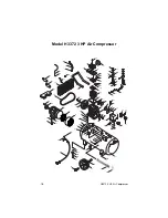
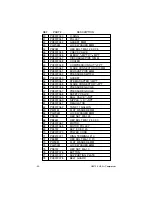
H3372 3 HP Air Compressor

-20

-

40

PH3372040

O-RING

41

PH3372041

PULLEY

42

PH3372042

GASKET 8MM

43

PLW04M 

LOCK WASHER 8MM

44

PB20M 

HEX BOLT M8-1.25 X 35

45

PH3372045

CHECK VALVE

46

PH3372046

ELBOW 

1

8

MPT X

1

16

MPT

47

PH3372047

DISCHARGE PIPE 12MM

48

PH3372048

COOLER

49

PH3372049

COMPRESSION NUT 

3

FPT

50

PH3370062

FLARE CONNECTOR ID10MM 

51

PH3372051

EXHAUST PIPE 6MM

52

PH3372052

PRESSURE SWITCH

53

PH3372053

GASKET 

54

PH3370057

STEM ADAPTER 

1

MPT

55

PH3370058

FLARE CONNECTOR 

3

FPT

56

PH3372056

PRESSURE GAUGE

57

PH3372057

PRESSURE GAUGE

58

PH3372058

SAFETY VALVE

59

PH3372059

BALL VALVE 

1

NPT

60

PH3372060

NIPPLE  

1

4

1

NPT

61

PH3372061

REGULATOR

62

PH3372062

TANK 11 GALLON

63

PW01M 

FLAT WASHER 8MM

64

PLW04M 

LOCK WASHER 8MM

65

PN03M 

HEX NUT M8-1.25

66

PB26M 

HEX BOLT M8-1.25 X 30

67

PH3372067

MOTOR

68

PH3372068

MOTOR PULLEY

69

PK41M 

KEY 8 X 8 X 40

70

PH3372070

POWER CORD

71

PH3372071

RING TERMINAL #10

72

PB08M 

HEX BOLT M6-1 X 20

73

PW03M 

FLAT WASHER 6MM

74

PLW03M 

LOCK WASHER 6MM 

75

PN01M 

HEX NUT M6-1.0

76

PH3372076

BUTTON

77

PH3372077

SUPPORTING PLATE

78

PH3372078

BELT GUARD

DESCRIPTION 

REF

PART #

Summary of Contents for H3372

Page 1: ...ION IN THIS MANUAL REPRESENTS THE CONFIGURATION OF THE MACHINE AS IT IS CURRENTLY BEING SHIPPED THE MACHINE CONFIGURATION CAN CHANGE AS PRODUCT IMPROVEMENTS ARE INCORPORATED IF YOU OWN AN EARLIER VERSION OF THE MACHINE THIS MANUAL MAY NOT EXACTLY DEPICT YOUR MACHINE CONTACT CUS TOMER SERVICE IF YOU HAVE ANY QUESTIONS ABOUT DIFFERENCES PREVIOUS VER SIONS ARE NOT AVAILABLE ONLINE 3 HP AIR COMPRESSOR...

Page 2: ...als are Lead from lead based paints Crystalline silica from bricks cement and other masonry products Arsenic and chromium from chemically treated lumber Your risk from these exposures varies depending on how often you do this type of work To reduce your exposure to these chemicals work in a well ventilated area and work with approved safety equipment such as those dust masks that are specially des...

Page 3: ...ention measures NOTICE Safety Instructions For Pneumatic Tools 1 KEEP ALL SAFETY DEVICES IN PLACE and in working order 2 REMOVE ADJUSTING KEYS AND WRENCHES Form a habit of checking to see that keys and adjusting wrenches are removed from tool before operation 3 KEEP WORK AREA CLEAN Cluttered areas and benches invite accidents 4 DO NOT USE IN DANGEROUS ENVIRONMENT DO NOT use pneumatic tools in damp...

Page 4: ...E THE RISK OF UNINTEN TIONAL STARTING DO NOT carry tool with hand on trigger and always disconnect from air when not in use Safety Instructions For Pneumatic Tools 18 DISCONNECT TOOLS before ser vicing and changing accessories 19 USE THE RECOMMENDED ACCESSORIES Consult the owner s manual for recommended accessories The use of improper accessories may cause risk of injury 20 CHECK DAMAGED PARTS Bef...

Page 5: ...e 8 AVOID TOUCHING THE TOP OF THE MOTOR HOUSING it will become hot during operation 9 MAKE SURE TO ADD OIL Use compressor oil or a non detergent 30 weight oil 10 NEVER LEAVE COMPRESSOR TURNED ON WHEN NO ONE IS AROUND A leak could develop caus ing compressor to run continuously causing overheating and possibly a fire 11 NEVER AIM THE AIR NOZZLE DIRECTLY AT YOURSELF OR OTH ERS Pressurized air can br...

Page 6: ...tures a powerful 220V 3 HP motor two cylinder aluminum pump with cast iron cylinder liners an incredible 10 9 CFM 40 PSI 9 1 CFM 90 PSI 11 gallon welded steel tank and a 115 PSI maximum working pressure The Model H3372 compressor fills its 11 gallon tank from 0 to 115 PSI in a little over a minute We are pleased to provide this manual with the Model H3372 It was written to encourage safety conside...

Page 7: ...nts for the needs of your particular compressor Also make sure the compressor is not operating in an environment where there are any explosive flammable or caustic fumes or gases A clear and well ventilated area is best for its safe operation Place the compressor on a solid and level surface Make sure that the hoses you attach to your pneumatic device will be unrestricted in movement and not subje...

Page 8: ... short ground ing reduces the risk of electric shock by providing a path of least resistance to dis perse electric current These machines are equipped with power cords having an equipment grounding conductor See Figure 1 The outlet must be properly installed and grounded in accordance with all local codes and ordinances Grounding Figure 1 Ground plug configuration If you find it necessary to use a...

Page 9: ...inder rings which deliver the compressed air Severe damage to the internal moving parts can occur if there is not adequate oil flow Check the oil level frequently and change the oil on a regular schedule Figure 2 Air filter attached to cylinder head Duty Cycle The Model H3372 3 HP Air Compressor should not be operated on more than a 50 duty cycle This means an air com pressor that pumps air for ov...

Page 10: ...ts too high See the Pressure Regulator sub section Operating this equipment has the potential for flying debris to cause eye injury Always wear safety glass es or goggles when operating equip ment Everyday glasses or reading glasses only have impact resistant lenses they are not safety glasses Be certain the safety glasses you wear meet the appropriate standards of the American National Standards ...

Page 11: ...g the drain valve simply turn the release nut to allow air to flow out of the tank The drain valve is shown in Figure 5 The drain valve is also used to drain condensation that builds up in the tank The safety valve automatically releases pressure if the tank reaches 130 PSI To manually release the air in the tank by using the safety drain valve 1 Locate the safety drain valve on the tank The drain...

Page 12: ...black ON OFF switch cover by removing the screw which is in the recess on the top of the cover Pull the black cover up and set it aside 5 Turn the pressure adjustment bolt Figure 9 a half turn clockwise to increase the tank pressure and a half turn counter clockwise to decrease the pressure 6 Connect the compressor to the power supply and start the compressor 7 If the PSI level still needs adjustm...

Page 13: ...ent air volume will not perform their function satisfactorily Figure 10 Quick connect couplers 3 Connect the tool using a good quality air line with an adequate length to reach from the compressor to the point of use Note Quick connect couplers shown in Figure 10 are a good option for fast and sure connection of tools and air hoses This accessory and many like it can be found in the Grizzly Catalo...

Page 14: ...ge on the bottom of the crankcase to make sure the oil level is at the prop er height 2 Drain the tanks of any condensation by opening the drain valve on the bot tom of the tank Note Depending upon the amount of use and the weather conditions a certain amount of condensed water may be released For longevity of the compressor seals and the air tools you connect it is best to keep the tanks free of ...

Page 15: ...the air compressor shown in Figure 11 The guard is attached to the compressor frame by the two mounting bolts shown in Figure 11 2 Loosen the four nuts one side shown in Figure 12 that secure the motor to the compressor frame so the motor can slide towards crankcase relieving the tension on the V belt 3 Remove the V belt from the motor pul ley and fly pulley 4 Install the new V belt 5 Reposition t...

Page 16: ...g hours or 30 days whichever comes first perform the following maintenance Replace the oil in the motor with com pressor oil use ISO 100 of SAE 30W viscosity non detergent type Make sure that all the fittings are tight Remove the air filter foam element shown in Figure 14 and rinse it out with water Allow it to dry and re install Figure 14 Air filter foam element Blow out any accumulated dirt betw...

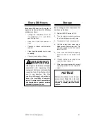
Page 17: ... excess pressure from tank The pressure gauge for the tank should read 15 20 PSI 5 Drain water from the tank by opening the drain valve on the bottom of the tank 6 Close the drain valve when all the water has been released 7 Store the air compressor in its normal operating position in a cool protected area Every 300 Hours Storage Like all power tools there is danger associated with operating this ...

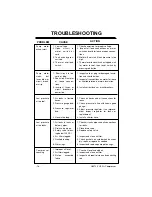
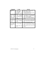
Page 18: ...o improve ment inspect regulator for leaks or replacement 4 Install a shorter hose 1 Check air tanks pipes and all connections for leaks 2 Close drain valve 3 Replace safety valve 4 Inspect and clean air filter 5 Check gaskets on cylinder head assem bly repair or replace as needed 6 Inspect and replace pump piston rings 1 Check oil level and add oil 2 Inspect and clean air filter 3 Inspect and rep...

Page 19: ...ief valve is relieving pressure too early test pressure relief and repair or replace 1 Clean dirt or debris from rubber mem brane of check valve after removing top nut 2 Repair or replace pressure switch 1 Open drain cocks on both tanks and make certain all condensation water is drained out 2 Remove delivery pipes clean out and replace PROBLEM CAUSE ACTION 1 Cooling fins dirty 2 Air filter clogged...

Page 20: ...47 48 10 43 65 72 74 73 86 83 84 55 45 63 64 17 65 54 53 52 58 16 15 9 8 13 14 39 12 56 60 59 28 29 80 38 27 3 24 25 26 30 4 2 11 7 6 5 18 34 31 32 33 22 20 19 37 21 23 35 36 1 9 29 40 44 46 49 51 57 61 63 63 64 64 65 66 66 75 77 78 63 63 85 87 88 91 92 94 Model H3372 3 HP Air Compressor ...

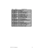
Page 21: ...PT 18 PH3372018 COMPRESSION RING 19 PH3372019 COMPRESSION RING 20 PH3372020 OIL RING 21 PH3372021 PISTON 22 PH3370017 PISTON PIN 12 X 37 5MM 23 PR49M INT RETAINING RING 12MM 24 PH3372024 CYLINDER TO CRANKCASE GASKET 25 PH3372025 CYLINDER 26 PH3372026 GASKET 27 PH3372027 VALVE PLANK 28 PB108M HEX BOLT M3 5 X 10 29 PLW09M LOCK WASHER 3MM 30 PH3372030 INLET VALVE PATCH 31 PH3372031 OUTLET VALVE PATCH...

Page 22: ...3370058 FLARE CONNECTOR 3 8 FPT 56 PH3372056 PRESSURE GAUGE 57 PH3372057 PRESSURE GAUGE 58 PH3372058 SAFETY VALVE 59 PH3372059 BALL VALVE 1 4 NPT 60 PH3372060 NIPPLE 1 4 X 1 8 NPT 61 PH3372061 REGULATOR 62 PH3372062 TANK 11 GALLON 63 PW01M FLAT WASHER 8MM 64 PLW04M LOCK WASHER 8MM 65 PN03M HEX NUT M8 1 25 66 PB26M HEX BOLT M8 1 25 X 30 67 PH3372067 MOTOR 68 PH3372068 MOTOR PULLEY 69 PK41M KEY 8 X ...

Page 23: ...ON FOOT 85 PB80M HEX BOLT M16 2 0 X 55 86 PH3372086 PNEUMATIC TIRE 8 5 87 PW08M FLAT WASHER 16MM 88 PN13M HEX NUT M16 2 0 89 PH3372089 FORK TERMINAL 10 90 PH3372090 CAPACITOR 250 MFD 250VAC 91 PH3372091 MOTOR FAN 92 PH3372092 FAN COVER 93 PH3372093 CAPACITOR COVER 94 PH3372094 CAPACITOR 40 MFD 400VAC 95 PH3372095 GRIZZLY LOGO LABEL 96 PH3372096 MACHINE ID LABEL DESCRIPTION REF PART ...

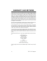
Page 24: ...or death injuries to persons or property or for incidental con tingent special or consequential damages arising from the use of our products To take advantage of this warranty contact us by mail or phone and give us all the details We will then issue you a Return Authorization Number which must be clearly posted on the outside as well as the inside of the carton We will not accept any item back wi...

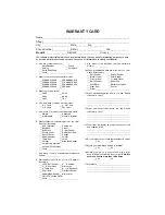
Page 25: ...you think your purchase represents good value ___Yes ___No 15 Would you recommend Grizzly to a friend ___Yes ___No 16 Would you allow us to use your name as a refer ence for Grizzly customers in your area Note We never use names more than three times ___Yes ___No 17 Comments ________________________________ _________________________________________ _________________________________________ _______...

Page 26: ...NC P O BOX 2069 BELLINGHAM WA 98227 2069 TAPE ALONG EDGES PLEASE DO NOT NAIL Name________________________________ Street________________________________ City______________State______Zip_______ Send a Grizzly Catalog to a friend Place Stamp Here ...

Reviews: