background image

G9984/G9985 (Mfd. Since 07/18)

-19-

SECTION 6: OPERATIONS

Once assembly is complete and adjustments are 
done to your satisfaction, you are ready to test run 
the machine.

Turn  on  the  power  supply  at  the  main  panel. 
Press the START button. Make sure that your fin-
ger is poised on the switch, just in case there is a 
problem. The machine should run smoothly, with 
little or no vibration or rubbing noises. Strange or 
unnatural noises should be investigated and cor-
rected before operating the machine further. 

If  you  cannot  easily  locate  the  source  of  an 
unusual  noise  or  vibration,  contact  our  Service 
Department for help.

Test Run

There are many types of sanding belts to choose 
from.  We  recommend  Aluminum  Oxide  for  gen-
eral  workshop  environments.  Below  is  a  chart 
that  groups  abrasives  into  different  classes,  and 
shows which grits fall into each-class.

The general rule of thumb is to sand a workpiece 
with  progressively  higher  grit  numbers,  with  no 
one grit increase of more than 100.

Sanding Belts

Disconnect power to the 

machine when perform-

ing any maintenance, 

assembly or adjust-

ments. Failure to do this 

may result in serious 

personal injury.

Wear safety glasses dur-

ing the entire operation 

process. Failure to com-

ply may result in serious 

personal injury.

Keep loose clothing 

rolled up and out of the 

way of machinery and 

keep hair pulled back.

Always wear a dust 
mask when operating 
the Model 

G9984/G9985

Using this  machine pro-
duces sawdust which 
may cause allergic reac-
tions or respiratory 
problems.

Grit

Type

24-36

40-60

80-100

120-180

220-360

Very Coarse

Coarse

Medium

Fine

Very Fine

Summary of Contents for G9984

Page 1: ...ARY 2019 RS WARNING NO PORTION OF THIS MANUAL MAY BE REPRODUCED IN ANY SHAPE OR FORM WITHOUT THE WRITTEN APPROVAL OF GRIZZLY INDUSTRIAL INC PRINTED IN TAIWAN V2 01 19 MODEL G9984 G9985 OSCILLATING EDG...

Page 2: ...g grinding tool integrity and the usage of personal protective equipment The manufacturer will not be held liable for injury or property damage from negligence improper training machine modifications...

Page 3: ...N UP 11 SITE CONSIDERATION 11 4 ASSEMBLY BEGINNING ASSEMBLY 12 RUBBER FEET 12 BASE SUPPORTS 13 5 ADJUSTMENTS POWER SWITCH 14 DUST COLLECTION 14 SANDING BELT ROTATION 15 SANDING BELT REPLACEMENT 15 SAN...

Page 4: ...he progression of symbols is described below Remember that safety messages by themselves do not eliminate danger and are not a substitute for proper accident prevention measures NOTICE Safety Instruct...

Page 5: ...On machines with magnetic contact starting switches there is a risk of starting if the machine is bumped or jarred Always disconnect from power source before adjusting or servicing Make sure switch i...

Page 6: ...r or in contact with sanding belt during operation ANY PROBLEM with the exception of belt tracking that is concerned at all with any moving parts or accessories must be investigated and corrected with...

Page 7: ...ectrician Figure 1 NEMA style L6 20 plug and outlet Figure 2 NEMA style L15 20 plug and outlet Grounding Prong is Hooked Current Carrying Prongs L6 20 GROUNDED LOCKING RECEPTACLE L6 20 LOCKING PLUG Gr...

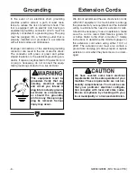
Page 8: ...ith your local municipality or a licensed electrician Grounding Extension Cords In the event of an electrical short grounding provides electric current a path of least resis tance to reduce the risk o...

Page 9: ...ety consider ations and cover general operating procedures It represents our effort to produce the best docu mentation possible If you have any comments regarding this manual please write to us at the...

Page 10: ...ack or fork lift can also be used Damage from improper moving methods may void the warranty Keep the lifting rings in a safe location where they will not become lost These rings will need to be re ins...

Page 11: ...for the sake of expedi ency replacements can be obtained at your local hardware store Figure 5 Parts layout Some metal parts may have sharp edges on them after they are formed Please examine the edge...

Page 12: ...23 4 3 LINES ARE 1MM APART LINES ARE 1 16 INCH APART 5 8 W A S H ER DIAM E T E R 9 16 W A S H ER DIA M E T E R 1 2 W A S H ER DIA M E T E R 12mm W A S H ER DIAM E T E R 10mm W A S H ER DIA M E T E R...

Page 13: ...e sufficient to carry the weight of the Model G9984 G9985 If you question the strength of your floor you can opt to reinforce it Ensure that the stand or bench you use with the Model G9984 G9985 is ca...

Page 14: ...shown in Figure 6 2 Do not overtighten the feet Cast iron threads are softer than the steel threads on the feet Overtightening can cause the cast iron threads to become stripped Rubber Feet Figure 6...

Page 15: ...achine base 2 Using 4 M10 1 5 x 30 hex bolts 4 10mm flat washers and 4 10mm lock washers secure the main machine base to the base supports as shown in Figure 7 Be sure the lock washer is between the h...

Page 16: ...agnetic power switch The Model G9984 G9985 must be turned ON to visually check the results of certain adjustments made to the sander however actual adjustments should never be performed while the mach...

Page 17: ...ly check the sand ing belt rotation Do not attempt to per form any adjustments to the sanding belt while the machine is connected to a power source Failure to unplug before adjusting the sanding belt...

Page 18: ...cen tered path across the rollers adjustment is necessary 3 Disconnect the machine from the power source 4 Loosen the check nut shown in Figure 12 5 Turn the adjustment knob counter clockwise to adjus...

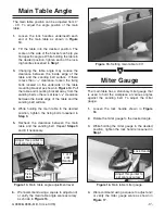
Page 19: ...desired position tighten each of the lock ing handles loosened in Step 1 3 Changing the table angle may reduce the clearance between the inside edge of the table and the sanding belt surface If there...

Page 20: ...osition tighten the lock handle loosened in Step 1 Side Table Angle Figure 19 Lock handle for side table angle The side table can be adjusted to accommodate a wide range of workpieces To adjust the si...

Page 21: ...um Oxide for gen eral workshop environments Below is a chart that groups abrasives into different classes and shows which grits fall into each class The general rule of thumb is to sand a workpiece wi...

Page 22: ...ts 2 Worn switch 3 Worn or damaged cords and plugs 4 Damaged or worn sanding belt 5 Any other condition that could hamper the safe operation of this machine General Tables Disconnect power to the mach...

Page 23: ...sted in Section 3 Introduction Additional information sources are necessary to realize the full potential of this machine Trade journals woodworking magazines and your local library are good places to...

Page 24: ...t at the time of printing but may not match your machine If you find this to be the case use the wiring diagram inside the motor junction box CAPACITORS INVERTERS Some capacitors and power inverters s...

Page 25: ...m 2T1 6T3 14NO 4T2 1L1 5L3 13NO 3L2 NHD 220V T1 T2 T3 98 17 18 A2 A1 95 97 ON 96 Ground Ground 1 PHASE 220 VAC 3 HP MOTOR MAGNETIC CONTACTOR SWITCH Start Capacitor 300MFD 250VAC Run Capacitor 20MFD 50...

Page 26: ...985 Revised Wiring Diagram 2T1 6T3 14NO 4T2 1L1 5L3 13NO 3L2 NHD 220V T1 T2 T3 98 17 18 A2 A1 95 97 ON 96 Ground Ground 3 PHASE 220 VAC 3 HP MOTOR MAGNETIC CONTACTOR SWITCH Ground Hot Hot Hot 15 15 PL...

Page 27: ...bs Net Weight 682lbs Crate Size 865 8 L x 281 4 W x 451 4 H Footprint 42 x 241 2 Construction Base Sheet Steel Table Aluminum Idler Roller Rubber 4 Drive Roller Rubber 9 Motor Type TEFC Capacitor Star...

Page 28: ...nstruction Base Sheet Steel Table Aluminum Idler Roller Rubber 4 Drive Roller Rubber 9 Motor Type Induction Horsepower 3 H P Phase Voltage Three Phase 220V Amps 9A Cycle and R P M 60 Hertz 1725 R P M...

Page 29: ...G9984 G9985 Mfd Since 07 18 27...

Page 30: ...BASE SUPPORT 40 P9984040 U HANDLE 15 P9984015 FLAT WASHER 10mm 41 P9984041 PHLP HD SCR M8 1 25 x 16 17 P9984017 SUPPORT 42 P9984042 HEX NUT M8 1 25 18 P9984018 FLAT WASHER 3 8 43 P9984043 STAR KNOB M...

Page 31: ...G9984 G9985 Mfd Since 07 18 29...

Page 32: ...112 HEX NUT M10 1 5 138 P9984138 FLAT WASHER 3 8 113 P9984113 LOCK WASHER 10mm 139 P9984139 LOCK WASHER 10mm 114 P9984114 FLAT WASHER 5 16 140 P9984140 HEX BOLT M10 1 5 X 30 115 P9984115 LOCK WASHER 5...

Page 33: ...G9984 G9985 Mfd Since 07 18 31 201V2 202 203 204 205 206 208 209 210 211 212 213V2 214 215 216 217 218 221V2 222 223 224...

Page 34: ...04 P9984204 HEX BOLT M10 1 5 X 30 216 P9984216 HEX BOLT M10 1 5 X 20 205 P9984205 LOCK HANDLE M10 1 5 X 25 217 P9984217 ADJUSTMENT BASE 206 P9984206 SHAFT 218 P9984218 SIDE SANDING TABLE 208 P9984208...

Page 35: ...G9984 G9985 Mfd Since 07 18 33...

Page 36: ...84309 LEVER 332 P9984332 FLAT WASHER 310 P9984310 HANDLE M10 1 5 333 P9984333 STAR KNOB 311 P9984311 CAP SCREW M10 1 5 X 30 335 P9984335 SHAFT 312 P9984312 LOCK WASHER 12mm 336 P9984336 BEARING NSK620...

Page 37: ...G9984 G9985 Mfd Since 07 18 35...

Page 38: ...9984435 PHLP HD SCR M8 1 25 X 20 417 P9984417 REDUCER CASING 436 P9984436 DRIVE WHEEL 418 P9984418 BRACKET 437 P9984437 FLAT WASHER 12 419 P9984419 FLAT WASHER 5 16 438 P9984438 LOCK WASHER 12mm 420 P...

Page 39: ...G9984 G9985 Mfd Since 07 18 37 NOTES...

Page 40: ...38 G9984 G9985 Mfd Since 07 18 NOTES...

Page 41: ...metalworker ____ 0 2 Years ____ 2 8 Years ____ 8 20 Years ____20 Years 6 How many of your machines or tools are Grizzly ____ 0 2 ____ 3 5 ____ 6 9 ____10 7 Do you think your machine represents a good...

Page 42: ...LINE FOLD ALONG DOTTED LINE GRIZZLY INDUSTRIAL INC P O BOX 2069 BELLINGHAM WA 98227 2069 Place Stamp Here Name_______________________________ Street_______________________________ City______________S...

Page 43: ...shall be tried in the State of Washington County of Whatcom We shall in no event be liable for death injuries to persons or property or for incidental contingent special or consequential damages arisi...

Page 44: ......

Reviews: