Grizzly G0952 Owner'S Manual Download Page 21

Model G0952 (Mfd. Since 09/21)

-19-

Installing/Changing 

Belt

The  grinding  belt  should  be  changed  whenever 
there  is  a  noticeable  change  in  grinding  quality/
performance.  You  may  also  need  to  change  grit 
sizes for quick material removal or finer finishes.

Required Belt Size ................................3" x 79"

Items Needed 

Qty

Belt Access Door Key........................................ 1
Replacement Belt .............................................. 1

To install/change belt: 

1.  DISCONNECT MACHINE FROM POWER!

2.  Use key to unlock and open belt access door.

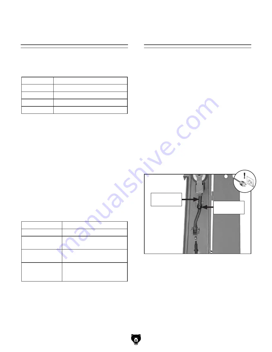
3.  Turn belt tension lock knob counterclockwise 

to loosen lock collar and release belt tension 
lever (see 

Figure 12).

Figure 12. Location of belt tension lock knob 

and belt tension lever.

Belt Tension

Lever

Belt Tension

Lock Knob

This  machine  uses  a  3"  x  79"  belt.  Below  is  a 
chart that groups abrasives into different classes, 
and shows which grits fall into each class.

The general rule of thumb is to grind a workpiece 
with  progressively  higher  grit  numbers.  Avoid 
skipping  grits;  the  larger  the  grit  increase,  the 
harder it will be to remove the scratches from the 
previous grit.

Ultimately,  the  type  of  metal  you  use  and  your 
stage of finish will determine the best grit types to 
install on your grinder.

Belts are also made with different materials, and 
your workpiece and intended operation will deter-
mine  which  belt  material  will  produce  the  best 
results for you. The chart below illustrates some 
common  belt  materials  and  the  situations  that 
they are most effective.

Grit

Class

36

Extra Coarse

60

Coarse

80–100

Medium

120–180

Fine

Choosing    

Grinding Belts

Belt Material

Operation

Aluminum Oxide Finishing. Ferrous metals.
Zirconia Alumina Finishing; wet or dry grinding. 

Ferrous metals, some steels.

Ceramic

Aggressive grinding; deburr-
ing. Heat-sensitive metals.

Silicon Carbide

Cutting;  stock  removal;  wet 
or  dry  grinding.  Cast  iron, 
steel, non-ferrous metals.

Summary of Contents for G0952

Page 1: ...ING NO PORTION OF THIS MANUAL MAY BE REPRODUCED IN ANY SHAPE OR FORM WITHOUT THE WRITTEN APPROVAL OF GRIZZLY INDUSTRIAL INC CS21945 PRINTED IN CHINA V1 10 21 MODEL G0952 3 X 79 METAL BELT GRINDER SAND...

Page 2: ...g grinding tool integrity and the usage of personal protective equipment The manufacturer will not be held liable for injury or property damage from negligence improper training machine modifications...

Page 3: ...on 14 Power Connection 15 Test Run 16 SECTION 4 OPERATIONS 17 Operation Overview 17 Workpiece Inspection 18 Grinding Tips 18 Choosing Grinding Belts 19 Installing Changing Belt 19 Checking Adjusting B...

Page 4: ...ade every effort to be exact with the instruc tions specifications drawings and photographs in this manual Sometimes we make mistakes but our policy of continuous improvement also means that sometimes...

Page 5: ...Use this machine with respect and caution to decrease the risk of operator injury If normal safety pre cautions are overlooked or ignored seri ous personal injury may occur No list of safety guideline...

Page 6: ...tment C Belt Access Door Opens and closes to allow for belt replacement and maintenance D Belt Access Door Lock Locks and releases belt access door using key C D Figure 2 Operational controls and comp...

Page 7: ...Height 19 x 16 x 48 in Must Ship Upright Yes Electrical Power Requirement 220V 3 Phase 60 Hz Full Load Current Rating 3 9A Minimum Circuit Size 15A Connection Type Cord Plug Power Cord Included Yes Po...

Page 8: ...sed PAGE 2 OF 2 Model G0952 Other Related Info Number of Dust Ports 1 Dust Port Size 3 in Other Specifications Country of Origin China Warranty 1 Year Approximate Assembly Setup Time 15 Minutes Serial...

Page 9: ...proof DANGEROUS ENVIRONMENTS Do not use machinery in areas that are wet cluttered or have poor lighting Operating machinery in these areas greatly increases the risk of accidents and injury MENTAL AL...

Page 10: ...moving parts or flying debris Make sure they are properly installed undamaged and working correctly BEFORE operating machine FORCING MACHINERY Do not force machine It will do the job safer and better...

Page 11: ...ce could cause it to be grabbed aggressively pulling hands into abrasive surface Firmly grasp workpiece in both hands and ease it into belt using light pressure AVOIDING ENTANGLEMENT Becoming entangle...

Page 12: ...ay result especially if connected to an undersized circuit To reduce the risk of these hazards avoid over loading the machine during operation and make sure it is connected to a power supply circuit t...

Page 13: ...roperly grounded If you ever notice that a cord or plug is damaged or worn discon nect it from power and immediately replace it with a new one Serious injury could occur if you connect machine to powe...

Page 14: ...ne This machine was carefully packaged for safe transport When unpacking separate all enclosed items from packaging materials and inspect them for shipping damage If items are damaged please call us i...

Page 15: ...hown 1 C Spark Tray Inside Machine 1 Figure 5 Inventory A C Figure 6 Minimum working clearances Electrical Connection Min 30 for Maintenance Wall 13 25 Children and visitors may be seriously injured i...

Page 16: ...Hole Figure 7 Popular method for anchoring machinery to a concrete floor Anchoring to Concrete Floors Number of Mounting Holes 4 Diameter of Mounting Hardware 7 16 Figure 8 Ducting attached to dust p...

Page 17: ...life of electrical components on your machine If you must use an extension cord refer to Extension Cords on Page 11 for more information Correcting Phase Polarity This sub section is provided for trou...

Page 18: ...help The Test Run consists of verifying the following 1 The belt tracks properly and will not come off the wheels during initial startup 2 the motor powers up and runs correctly and 3 the E Stop cover...

Page 19: ...l times Entanglement can result in death amputation or severe crushing injuries To complete a typical operation the operator does the following 1 Examines workpiece to make sure it is suit able for gr...

Page 20: ...nder Before grinding inspect all workpieces for the following Flammable Workpiece Workpieces with unstable chemical elements like magne sium may catch fire or create explosion hazards when introduced...

Page 21: ...ch class The general rule of thumb is to grind a workpiece with progressively higher grit numbers Avoid skipping grits the larger the grit increase the harder it will be to remove the scratches from t...

Page 22: ...ded Qty Belt Access Door Key 1 Protective Gloves 1 Pair To check adjust belt tracking 1 DISCONNECT MACHINE FROM POWER 2 Use key to unlock and open belt access door 3 Standing at front of machine rotat...

Page 23: ...ay from motor rotate belt tracking adjustment knob clockwise 1 4 turn see Figure 16 Figure 16 Location of belt tracking adjustment knob Figure 17 Location of work rest and lock knob Work Rest Lock Kno...

Page 24: ...s a workpiece against the Model G0952 has a contact wheel While a platen can only be used for flat or convex workpieces the contact wheel also allows for workpieces that are concave see Figure 19 Flat...

Page 25: ...ir P100 Breathing metal dust could cause severe respira tory illnesses If you work around dust everyday a half mask respirator can be a lifesaver Also compatible with safety glasses Basic Eye Protecti...

Page 26: ...ories T28774 T58553 G6176 T27588 T26685 ISO 32 Moly D Machine Oil 1 Gal T23963 ISO 32 Moly D Machine Oil 5 Gal Moly D oils are some of the best we ve found for maintaining the critical components of m...

Page 27: ...ts maintenance or service Cleaning the Model G0952 is relatively easy Vacuum excess shavings and wipe off any remaining dust with a dry cloth Never use com pressed air to blow away dust as airborne pa...

Page 28: ...rrect motor wiring connections Page 29 6 Fix broken wires or disconnected corroded connections Page 29 7 Replace switch 8 Replace motor Machine stalls or is underpowered 1 Excessive feed pressure appl...

Page 29: ...ct wheel is worn 1 Make sure tension lever is locked in tensioning position Page 19 2 Replace grinding belt Page 19 3 Replace contact wheel Belt tracks to one side under load 1 Grinding belt tracking...

Page 30: ...t at the time of printing but may not match your machine If you find this to be the case use the wiring diagram inside the motor junction box CAPACITORS INVERTERS Some capacitors and power inverters s...

Page 31: ...AGE 28 V2 U2 W2 W1 V1 U1 220V MOTOR MAG ON OFF SWITCH KEDU KJD18 15 15 Plug as recommended Ground Hot Hot Hot 220 VAC 3 Phase W Z G X W V U 5 3 1 6 4 2 A1 W V U W U V L1 L2 L3 Wiring Diagram Figure 31...

Page 32: ...26 27 28 29 30 31 32 33 34 35 36 37 38 39 40 41 18 25 9 1 2 3 20 1 20 2 20 3 20 4 20 5 20 6 42 43 42 1 42 2 42 6 42 5 42 3 20 7 42 4 44 Main SECTION 9 PARTS We do our best to stock replacement parts w...

Page 33: ...0 X 1 7MM 35 P0952035 EYE SHIELD 14 P0952014 DRIVE WHEEL 36 P0952036 KNOB BOLT M6 1 X 10 18 LOBE D24 15 P0952015 FOOT 37 P0952037 KNOB BOLT M8 1 25 X 25 3 LOBE D36 16 P0952016 FLAT HD SCR M4 7 X 8 38...

Page 34: ...ver touch moving sandpaper 7 Always grind in accordance with directional arrows on machine 8 Make sure grinder is properly assembled adjusted and stable before operating Only operate with all guards i...

Page 35: ...rty or for incidental contingent special or consequential damages arising from the use of our products The manufacturers reserve the right to change specifications at any time because they constantly...

Page 36: ......

Reviews: