-24-
Model G0879 (Mfd. Since 6/19)
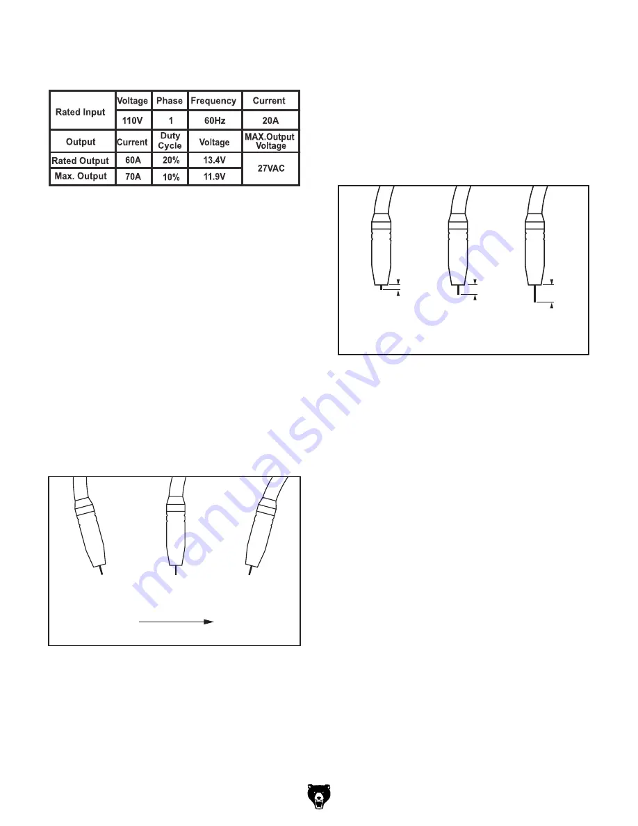
Figure 22. Welding angle.
Perpendicular
15°
Push
15°
Drag
(Welding Direction)
Figure 21. Welding specification chart.
Figure 23. Contact tip to work distance.
<
3
⁄
16
"
3
⁄
16
"-
1
⁄
4
"
>
1
⁄
4
"
Bad
Bad
Good
6. Set desired settings for type of intended weld
(see
Figure 21).
7. Position welding gun so it is aimed perpen-
dicular to intended weld location.
Note: Wire electrode has a live electrical cur-
rent when machine is turned
ON and will arc
immediately when wire makes contact with
grounded workpiece. Trigger will only begin
to feed wire out of gun.
8. Tilt gun 15–20° along direction of weld to
allow better visibility of weld location (see
Figure 22).
Note: Flux core welds can be made by "drag-
ging," "pushing," or staying perpendicular to
weld. However, it is generally recommended
that the operator utilize the "dragging" tech-
nique to avoid slag inclusions in welds.
9. Squeeze trigger so wire begins to feed
into weld. Once wire makes contact with
workpiece, arc will start and weld pool will
begin to form. Maintain consistent dis-
tance between contact tip and workpiece of
3
⁄
16
"—
1
⁄
4
" (see
Figure 23).
Note: Keep welding gun cable as straight as
possible so as to not inhibit wire feed.
10. Watch molten weld pool form. Controlling
weld pool with welding gun will dictate how
weld bead forms. Size of weld pool dictates
how fast to move welding gun.
— If weld burns through workpiece, either
move gun faster or set machine to “LOW”
amperage setting.
— If base metal is not being penetrated by
weld, either slow down gun travel speed or
set machine to “HIGH” amperage setting.
11. When weld is complete, release trigger on
welding gun to stop weld.
12. Allow machine to cool, then turn machine
OFF.
Summary of Contents for G0879
Page 36: ......


