


Model G0803Z (Mfd. Since 12/18)
-29-
Workpiece
Inspection
Setting Upper Blade
Guide Height
Some workpieces are not safe to cut or may
require modification before they are safe to cut.
Before cutting, inspect all workpieces for the
following:
•
Material Type: This machine is intended for
cutting natural and man-made wood prod-
ucts, laminate covered wood products, and
some plastics. Cutting drywall or cementious
backer board creates extremely fine dust
and may reduce the life of the bearings. This
machine is NOT designed to cut metal, glass,
stone, tile, etc.; cutting these materials with a
table saw may lead to injury.
•
Foreign Objects: Nails, staples, dirt, rocks
and other foreign objects are often embed-
ded in wood. While cutting, these objects
can become dislodged and hit the operator,
cause kickback, or break the blade, which
might then fly apart. Always visually inspect
your workpiece for these items. If they can't
be removed, DO NOT cut the workpiece.
•
Large/Loose Knots: Loose knots can
become dislodged during the cutting opera-
tion. Large knots can cause kickback and
machine damage. Choose workpieces that
do not have large/loose knots or plan ahead
to avoid cutting through them.
•
Wet or "Green" Stock: Cutting wood with a
moisture content over 20% causes unneces-
sary wear on the blades, increases the risk of
kickback, and yields poor results.
•
Excessive Warping: Workpieces with exces-
sive cupping, bowing, or twisting are danger-
ous to cut because they are unstable and
often unpredictable when being cut. DO NOT
use workpieces with these characteristics!
•
Minor Warping: Workpieces with slight cup-
ping can be safely supported if the cupped
side is facing the table or the fence. On
the contrary, a workpiece supported on the
bowed side will rock during a cut and could
cause kickback or severe injury.
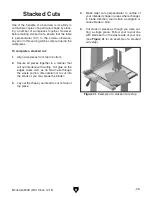
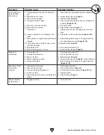
When cutting, the blade guides must always be
positioned so they just clear (no more than
1
⁄
4
") the
workpiece. The guide post, shown in
Figure 33,
allows the upper blade guide assembly to be
quickly adjusted for height.
To adjust height of upper blade guides:
1. DISCONNECT MACHINE FROM POWER!
2. Loosen guide post lock knob.
3. Using guide post control knob, adjust height
of the guide post so that blade guide assem-
bly just clears (no more than
1
⁄
4
") workpiece.
4. Re-tighten lock knob to secure setting.
Figure 33. Guide post, lock, and control knobs.
Guide
Post
Guide Post
Lock Knob
Guide Post
Control
Knob
Summary of Contents for G0803Z
Page 60: ......


