background image

-40-

Model G0781 (Mfd. Since 2/15)

READ ELECTRICAL SAFETY 

ON PAGE 38!

DRO 

L2

A-

F-

F+

L1

A+

P1

P2

P3

To Plug

ON/OFF Switch

3

1

4

2

B4K7

Mornsun

LD01-10B05

Capacitor

110 VAC

Neutral

Hot

Ground

5-15 Plug

(Pre-Wired)

Rear Panel

Front Panel

(Viewed From Backside)

Side Panel

(Viewed From Backside)

Bottom Inside Panel

(Viewed From Backside)

JD011

J2

J1

Power

Light

110V

FWD/REV Switch

E-TEN1322 15A/250VAC

Potentiometer

Circuit Board

JD-111 REVA 141022

Mill/Drill 

Motor 

120V 5A

Single Phase

3/4 HP 

5000 RPM

KEDU

KJD12

120V

FUSE 8AL250V

RPM 

Sensor

Wiring Diagram

Summary of Contents for G0781

Page 1: ...ls manufactured since 02 15 COPYRIGHT AUGUST 2015 BY GRIZZLY INDUSTRIAL INC REVISED OCTOBER 2015 JH WARNING NO PORTION OF THIS MANUAL MAY BE REPRODUCED IN ANY SHAPE OR FORM WITHOUT THE WRITTEN APPROVAL OF GRIZZLY INDUSTRIAL INC JH17413 PRINTED IN CHINA V1 10 15 ...

Page 2: ...ng grinding tool integrity and the usage of personal protective equipment The manufacturer will not be held liable for injury or property damage from negligence improper training machine modifications or misuse Some dust created by power sanding sawing grinding drilling and other construction activities contains chemicals known to the State of California to cause cancer birth defects or other repr...

Page 3: ...ns Adjustments 19 SECTION 4 OPERATIONS 20 Operation Overview 20 Spindle Speed 21 Using Spindle 22 Downfeed Controls 22 Adjusting 23 Headstock 23 Moving Table 24 Installing Removing Tooling 25 SECTION 5 ACCESSORIES 26 SECTION 6 MAINTENANCE 29 Schedule 29 Cleaning and Protecting 29 Lubrication 29 SECTION 7 SERVICE 31 Troubleshooting 31 Adjusting Gibs 33 Head Counterbalance Spring 34 Replacing Fuse 3...

Page 4: ...p Before calling make sure you write down the Manufacture Date and Serial Number from the machine ID label see below This information is required for us to provide proper tech support and it helps us determine if updated documenta tion is available for your machine Manufacture Date Serial Number Manual Accuracy We stand behind our machines If you have ques tions or need help contact us with the in...

Page 5: ...is manual Spindle Power Light Way Cover Motor Spindle Direction Switch Work Table Y Axis Lock Lever Limit Block Speed Range Lever Headstock Lock Lever Coarse Downfeed Handle Y Axis Handwheel X Axis Lock Lever Chuck X Axis Handwheel Fine Downfeed Handwheel Drawbar Cap Variable Speed Dial ON OFF Switch w Emergency Stop Button Column Tilt Nut Spindle Speed Digital Readout DRO ...

Page 6: ...ng operations for rapid drilling or plunge cutting Spring assisted return auto matically returns spindle to top position when released F Headstock Lock Lever Locks headstock in position along column G Speed Range Lever Selects low gear for maximum torque from 50 1000 RPM or high gear for 120 2000 RPM Refer to Figures 1 2 and the following descrip tions to become familiar with the basic controls an...

Page 7: ... Power Requirement 110V Single Phase 60Hz Full Load Current Rating 5A Minimum Circuit Size 15A Connection Type Cord Plug Power Cord Included Yes Power Cord Length 6 ft Power Cord Gauge 18 AWG Plug Included Yes Included Plug Type 5 15 Switch Type ON OFF Push Button Switch w Safety Cover Motors Main Horsepower 600W 3 4 HP Phase Single Phase Amps 5A Speed 5000 RPM Type Universal Brush Type Motor Powe...

Page 8: ... R 8 Number of Vertical Spindle Speeds Variable Range of Vertical Spindle Speeds 50 1000 100 2000 RPM Drawbar Thread Size 7 16 20 Drawbar Length 5 1 2 in Spindle Bearings Ball Bearings Construction Spindle Housing Quill Cast Iron Table Precision Ground Cast Iron Head Cast Iron Column Base Cast Iron Base Cast Iron Paint Type Finish Enamel Other Specifications Country of Origin China Warranty 1 Year...

Page 9: ...d proof DANGEROUS ENVIRONMENTS Do not use machinery in areas that are wet cluttered or have poor lighting Operating machinery in these areas greatly increases the risk of accidents and injury MENTAL ALERTNESS REQUIRED Full mental alertness is required for safe operation of machin ery Never operate under the influence of drugs or alcohol when tired or when distracted For Your Own Safety Read Instru...

Page 10: ... moving parts or flying debris Make sure they are properly installed undamaged and working correctly BEFORE operating machine FORCING MACHINERY Do not force machine It will do the job safer and better at the rate for which it was designed NEVER STAND ON MACHINE Serious injury may occur if machine is tipped or if the cutting tool is unintentionally contacted STABLE MACHINE Unexpected movement dur i...

Page 11: ...nce power is restored You can be seriously injured or killed by getting clothing jewelry or long hair entangled with rotating cutter spindle You can be severely cut or have fingers amputated from contact with rotating cutters You can be blinded or struck by broken cutting tools metal chips workpieces or adjustment tools thrown from the rotating spindle with great force To reduce your risk of serio...

Page 12: ...ngth of time damage overheating or fire may result especially if connected to an undersized circuit To reduce the risk of these hazards avoid over loading the machine during operation and make sure it is connected to a power supply circuit that meets the specified circuit requirements For your own safety and protection of property consult an electrician if you are unsure about wiring practices or ...

Page 13: ...ord size gets longer and the gauge size gets smaller higher gauge numbers indicate smaller sizes Any extension cord used with this machine must be in good condition and contain a ground wire and matching plug receptacle Additionally it must meet the following size requirements Minimum Gauge Size 14 AWG Maximum Length Shorter is Better 50 ft Grounding Plug Requirements Figure 3 Typical 5 15 plug an...

Page 14: ...g machine or some of its parts To reduce this risk get help from other people and use a forklift or other lifting equipment rated for weight of this machine Keep hair clothing and jewelry away from mov ing parts at all times Entanglement can result in death amputation or severe crushing injuries Unpacking SUFFOCATION HAZARD Keep children and pets away from plastic bags or packing materials shipped...

Page 15: ...his list care fully check around inside the machine and packaging materials Often these items get lost in packaging materials while unpack ing or they are pre installed at the factory K A C D E G B I J L M F H N O P Small Item Inventory Figure 4 Qty A Toolbox 1 B Spanner Wrench 38 42 Hook Type 1 C Open End Wrench 36mm 1 D Spare Fuse 1 E Spindle Pin 1 F Drawbar 1 G Drill Chuck Arbor 1 H Open End Wr...

Page 16: ...r the following Disposable rags Cleaner degreaser WD 40 works well Safety glasses disposable gloves Plastic paint scraper optional Basic steps for removing rust preventative 1 Put on safety glasses 2 Coat the rust preventative with a liberal amount of cleaner degreaser then let it soak for 5 10 minutes 3 Wipe off the surfaces If your cleaner degreas er is effective the rust preventative will wipe ...

Page 17: ...s important for safe operation and lon gevity of machine components For best results operate this machine in a dry environment that is free from excessive moisture hazardous chemi cals airborne abrasives or extreme conditions Extreme conditions for this type of machinery are generally those where the ambient temperature range exceeds 41 104 F the relative humidity range exceeds 20 95 non condensin...

Page 18: ...n and causing accidental injury or damage The strongest mounting option is a Through Mount see example below where holes are drilled all the way through the workbench and hex bolts washers and hex nuts are used to secure the machine in place Machine Base Workbench Hex Bolt Flat Washer Flat Washer Lock Washer Hex Nut Figure 8 Through Mount setup To lift and place machine 1 Move shipping crate next ...

Page 19: ...he test run consists of the following 1 The motor powers up and runs correctly and 2 the Emergency Stop button stops spindle rotation To test run machine 1 Clear all setup tools away from machine 2 Make sure machine is properly lubricated see Page 29 3 Ensure there are no obstructions around or underneath spindle 4 Press red Emergency Stop button see Figure 11 on Page 18 5 Connect mill drill to po...

Page 20: ...nd tear of spindle components once the machine is placed into operation 7 Place spindle direction switch in FOR Forward position Lift red Emergency Stop button to access ON OFF switch and to reset Emergency Stop function then press green button Spindle will not rotate until variable speed dial is turned clockwise from the 0 on control panel When operating correctly machine runs smoothly with littl...

Page 21: ...ences re adjust them To perform spindle break in process 1 Successfully complete Test Run procedure beginning on Page 17 2 Open Emergency Stop button cover and press green button to start spindle 3 Shift speed range lever in LOW position and run spindle at 300 RPM for a minimum of 10 minutes in each direction FWD and REV 4 Repeat Step 3 at 600 RPM for 5 minutes in each direction 5 Turn mill drill ...

Page 22: ... machine If you are not experienced with this type of machine WE STRONGLY RECOMMEND that you seek additional training outside of this manual Read books magazines or get formal training before beginning any proj ects Regardless of the content in this sec tion Grizzly Industrial will not be held liable for accidents caused by lack of training To reduce risk of eye or face injury from flying chips al...

Page 23: ...he diameter of the cutting tool as noted below Using the correct spindle speed is important for safe and satisfactory results as well as maximiz ing tool life To set the spindle speed for your operation you will need to 1 Determine the best spindle speed for the cutting task and 2 configure the spindle controls to match the closest spindle speed Cutting speed typically defined in feet per minute F...

Page 24: ... rotated The fine downfeed handwheel graduated dial measures spindle movement in 0 001 increments with one full revolution equaling 0 060 of spindle travel The coarse downfeed handle and fine downfeed handwheel see Figure 14 move the spindle up and down for various milling drilling operations In the following example the fine downfeed controls are used to mill 0 010 off a workpiece 1 Use course do...

Page 25: ...eadstock Tool Needed Qty Wrench 36mm 1 To tilt headstock 1 DISCONNECT MACHINE FROM POWER 2 Support headstock with one hand then loos en headstock column tilt nut Note Column locking pin will engage when headstock column reaches 0 on tilt scale 3 Pull column locking pin outward Headstock will now freely tilt if pushed or pulled by hand into place DO NOT let go of headstock while column tilt nut is ...

Page 26: ...Y axis Longitudinal X Axis Travel Left Right Cross Y Axis Travel In Out Figure 17 Directions of table movement Loosen X axis lock lever shown in Figure 18 Turn X axis handwheels to adjust work table to desired location Tighten X axis lock lever before turning machine ON Both the X and Y axis feature table locks To ensure unexpected movement of the table does not occur during precision operations u...

Page 27: ...s shown in Figure 21 Note Do not overtighten drawbar Overtightening makes tool removal difficult and may damage arbor and threads 6 Re install drawbar cap and motor cover Figure 19 3 16mm drill chuck joined with R 8 arbor Key Slot Tools Needed Qty Spindle Pin 1 Wrench 10mm 1 Brass Hammer 1 To remove tooling 1 DISCONNECT MACHINE FROM POWER 2 Remove drawbar cap and secure spindle with spindle pin Un...

Page 28: ... five piece set of 1 2 HSS bor ing bars 1 2 to 3 4 adapter wrenches and fitted case T26485 58 Pc Clamping Kit This clamping kit includes 24 studs four studs each 3 4 5 6 7 and 8 long 6 step block pairs 6 T nuts 6 flange nuts 4 coupling nuts and 6 end hold downs The Model T26485 set fits 7 16 T slots and includes 3 8 16 studs Racks can be bolted to the wall or side of machine for easy access Figure...

Page 29: ...th 1 2 shanks graduated dial in 0 001 0 05 and 0 025 actual motion and a carrying case Figure 27 H5939 2 Boring Head Set G9815 Thin Parallel Set 10 Pairs G5646 10 Pc Precision Angle Block Set Speed set up production and inspection with the Grizzly Precision Angle Block Set and Thin Parallel Set made from hardened and precision ground steel Each set offers a wide range of sizes for any job Figure 2...

Page 30: ...g slots Figure 33 G5758 Tilt Table Figure 31 T24799 and T24800 Precision Parallel Blocks T24799 1 2 3 Precision Parallel Blocks T24800 2 4 6 Precision Parallel Blocks These blocks are extremely handy for layout and set up work Matched blocks are hardened and precision ground so all six sides are square to within 0 0003 T24800 T24799 Figure 32 H7527 6 Rotary Table w Div Plates H7527 6 ROTARY TABLE ...

Page 31: ...rom unpainted cast iron surfaces of mill drill and treat with a non staining lubricant after cleaning Protect other unpainted cast iron surfaces with regular applica tions of ISO 68 oil Cleaning and Protecting This mill drill requires regular lubrication to main tain smooth movement and ensure long lasting operation An essential part of lubrication is cleaning the components before lubricating the...

Page 32: ...lean X axis leadscrew Allow leadscrew to dry 6 Apply thin coat of ISO 68 machine oil to exposed X axis leadscrew threads Figure 37 X axis leadscrew lubrication point X Axis Leadscrew Table and Column Ways Lube Type Model SB1365 or ISO 68 Equivalent Lube Amount Thin Coat Lubrication Frequency 8 hrs of Operation Tool Needed Qty Standard Screwdriver 1 Disconnect each column way cover and move the tab...

Page 33: ...ce Machine stalls or is overloaded 1 Machine undersized for task 2 Wrong workpiece material 3 Dull tooling 4 Motor wired incorrectly 5 Motor overheated 6 Motor brushes at fault 7 Motor potentiometer at fault 8 Spindle rotation switch at fault 1 Use correct cutter bit reduce feed rate reduce spindle RPM use coolant if possible 2 Use correct type size of metal 3 Sharpen replace tooling 4 Wire motor ...

Page 34: ...t to workpiece use slower feed rate 6 Replace unbalanced chuck replace resharpen cutter Table is hard to move 1 Table locks are tightened down 2 Chips have loaded up on ways 3 Ways and leadscrew need lubrication 4 Gibs are too tight 1 Make sure table locks are fully released 2 Frequently clean away chips during operations 3 Lubricate ways Page 30 4 Adjust gibs Page 33 Headstock is hard to raise 1 ...

Page 35: ...ench 3mm 1 Wrench 10mm 1 To adjust gibs 1 DISCONNECT MACHINE FROM POWER 2 Make sure desired X Y and Z axis lock lever is loose 3 Loosen hex nuts on gib screws along desired gib adjustment see Figure 38 4 Loosen set screws and move sliding device back and forth to make sure gibs are loose then tighten set screws until you feel light resistance in the handwheel 5 Use hex wrench to prevent set screws...

Page 36: ... Spring Head counterbalance spring is under high tension DO NOT remove the cover or the spring The spring will rapidly uncoil caus ing personal injury Replacing Fuse This machine features a on board fuse designed to protect sensitive electrical parts in the event of electrical overload If the spindle fails to start replace the fuse 1 DISCONNECT MACHINE FROM POWER 2 Locate black fuse holder see Fig...

Page 37: ...ch 4mm 1 Standard Screwdriver 2 1 To inspect and replace motor brushes 1 DISCONNECT MACHINE FROM POWER 2 Remove motor cover by removing two cap screws see Figure 42 3 Unscrew one of the brush caps see Figure 43 Figure 43 Removing motor brush cap Figure 44 Inserting new motor brush 4 Remove old brush assembly If brush is worn down to less than 1 4 replace it with a new one Otherwise re install old ...

Page 38: ...ter it is mounted rather than tram ming the spindle to the table Tools Needed Qty Dial Test Indicator with at least 0 0005 resolution 1 Indicator Holder mounted on the quill spindle 1 Precision Parallel Block at least 9 in length 1 Note A precision ground plate can be substi tuted for the parallel blocks Keep in mind that the farther the indicator point can be placed from the spindle axis the more...

Page 39: ...ount by rotating the head left or right Repeat Steps 6 7 until you are satisfied with the spindle axis alignment along the table X axis Note Keep one of the rotation lock bolts just snug so the head does not move loosely while you adjust it Remember to tighten all the rotation lock bolts after adjusting the head 8 Place parallel block directly under spindle and across width of table as illustrated...

Page 40: ...nt at the time of printing but may not match your machine If you find this to be the case use the wiring diagram inside the motor junction box CAPACITORS INVERTERS Some capacitors and power inverters store an electrical charge for up to 10 minutes after being disconnected from the power source To reduce the risk of being shocked wait at least this long before working on capacitors EXPERIENCING DIF...

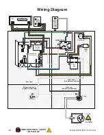
Page 41: ... ON PAGE 38 Wiring Overview Figure 49 G0781 wiring overview Power Cord JD 111 Circuit Board Power Light FWD REV Switch Potentiometer Rear Panel Side Panel KEDU KJD12 Switch Bottom Inside Panel Motor Inside Cover Fuse Holder Front Panel Spindle Speed DRO ...

Page 42: ...al Hot Ground 5 15 Plug Pre Wired Rear Panel Front Panel Viewed From Backside Side Panel Viewed From Backside Bottom Inside Panel Viewed From Backside JD011 J2 J1 Power Light 110V FWD REV Switch E TEN1322 15A 250VAC Potentiometer Circuit Board JD 111 REVA 141022 Mill Drill Motor 120V 5A Single Phase 3 4 HP 5000 RPM KEDU KJD12 120V FUSE 8AL250V RPM Sensor Wiring Diagram ...

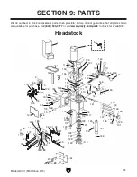
Page 43: ...82 1 2 3 5 6 7 9 10 11 12 13 15 16 18 171 101 102 103 104 105 106 107 108 109 110 111 112 113 114 116 117 118 119 120 121 122 123 125 126 127 128 129 130 131 132 133 135 137 138 141 143 144 146 148 149 150 151 153 154 155 156 157 158 159 160 161 162 163 164 165 166 167 168 169 170 12 18 120 107 113 134 142 149 150 163 164 121 11 5 1 5 2 151 111 14 17 19 21 22 23 24 26 27 28 29 187 31 36 18 172 32 ...

Page 44: ...81155 BEVEL GEAR 31T 27 P0781027 POWER LIGHT 110VAC GREEN 10MM 156 P0781156 KEY 4 X 4 X 20 28 P0781028 HEX NUT M10 1 5 THIN 157 P0781157 PINION SHAFT 29 P0781029 TOGGLE SWITCH E TEN1322 REVERSING 158 P0781158 ROLL PIN 4 X 20 30 P0781030 POTENTIOMETER B4K7 4 7KOHM 159 P0781159 GEAR HOUSING 31 P0781031 FLAT WASHER 11MM 160 P0781160 ADJUSTABLE HANDLE 45L M6 1 X 25 32 P0781032 HEX NUT M12 1 75 THIN 16...

Page 45: ...PLATE ALUMINUM 228 P0781228 ACORN NUT M6 1 208 P0781208 Z AXIS INDICATOR 229 P0781229 COLUMN LOCK 209 P0781209 HEADSTOCK ANGLE SCALE 230 P0781230 COMPRESSION SPRING 211 P0781211 CAP SCREW M10 1 5 X 35 231 P0781231 LOCK PIN 212 P0781212 COLUMN COVER 232 P0781232 LOCK SLEEVE 213 P0781213 ACORN NUT M8 1 25 233 P0781233 HEX NUT M24 3 214 P0781214 FLAT WASHER 8MM 234 P0781234 CUT WASHER 24 X 95MM 215 P...

Page 46: ... P0781310 FRONT WAY COVER 330 P0781330 X AXIS GIB 311 P0781311 FRONT WAY BAR 331 P0781331 X AXIS LEADSCREW NUT 312 P0781312 REAR WAY BAR 332 P0781332 FLAT SPRING FOR HANDWHEEL 313 P0781313 PHLP HD SCR M6 1 X 8 333 P0781333 FLAT WASHER 8MM 314 P0781314 REAR WAY COVER 334 P0781334 KEY 3 X 3 X 16 315 P0781315 REAR WAY COLUMN BAR 335 P0781335 ADJUSTABLE HANDLE 45L M6 1 X 25 316 P0781316 Y AXIS BEARING...

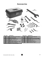
Page 47: ...403 DRAWBAR 7 16 20 X 5 1 2 412 P0781412 HEX WRENCH SET 2 2 5 3 4 5 6 8MM 404 P0781404 DRILL CHUCK ARBOR R8 X B16 413 P0781413 HANDWHEEL HANDLE 36L M8 1 25 X 10 REV 405 P0781405 TOOLBOX 414 P0781414 HEX NUT M8 1 25 406 P0781406 WRENCH 36MM OPEN END 415 P0781415 T SLOT NUT 1 2 X M8 1 25 407 P0781407 FUSE 8A 250V 0 25 FAST ACTING GLASS 416 P0781416 STUD UDE M8 1 25 X 45 11 25 408 P0781408 SPANNER WR...

Page 48: ...HIELD SAFETY GLASSES 1 5W X 2 5H 510 P0781510 SPEED RANGE LABEL 505 P0781505 READ MANUAL LABEL 511 P0781511 SPEED RANGE NOTICE LABEL 506 P0781506 MACHINE ID LABEL 512 P0781512 GRIZZLY PUTTY TOUCH UP PAINT 501 502 503 504 505 506 507 508 509 510 511 512 Safety labels help reduce the risk of serious injury caused by machine hazards If any label comes off or becomes unreadable the owner of this machi...

Page 49: ... metalworker ____ 0 2 Years ____ 2 8 Years ____ 8 20 Years ____20 Years 6 How many of your machines or tools are Grizzly ____ 0 2 ____ 3 5 ____ 6 9 ____10 7 Do you think your machine represents a good value _____Yes _____No 8 Would you recommend Grizzly Industrial to a friend _____Yes _____No 9 Would you allow us to use your name as a reference for Grizzly customers in your area Note We never use ...

Page 50: ...D LINE FOLD ALONG DOTTED LINE GRIZZLY INDUSTRIAL INC P O BOX 2069 BELLINGHAM WA 98227 2069 Place Stamp Here Name_______________________________ Street_______________________________ City______________State______Zip______ Send a Grizzly Catalog to a friend ...

Page 51: ... shall be tried in the State of Washington County of Whatcom We shall in no event be liable for death injuries to persons or property or for incidental contingent special or consequential damages arising from the use of our products To take advantage of this warranty contact us by mail or phone and give us all the details We will then issue you a Return Number which must be clearly posted on the o...

Page 52: ......
Reviews: