Model G0781 (Mfd. Since 2/15)
-33-
Adjusting Gibs
The gibs affect the accuracy of the work table by
restricting slide movements along their ways.
Screws on each axis end allow gib adjustment to
increase or decrease the friction between the slid-
ing surfaces of the ways.
The goal of gib adjustment is to remove unneces-
sary sloppiness without causing the X-, Y- and
Z-axis ways to bind. Tight gibs make the move-
ments more accurate, but harder to perform.
Loose gibs make the movements sloppy, but
easier to perform.
Tip: Many experienced machinists adjust the gibs
until there is just a slight drag in table movement.
Tools Needed:
Qty
Hex Wrench 3mm .............................................. 1
Wrench 10mm ................................................... 1
To adjust gibs:
1. DISCONNECT MACHINE FROM POWER!
2. Make sure desired X-, Y- and Z-axis lock lever
is loose.
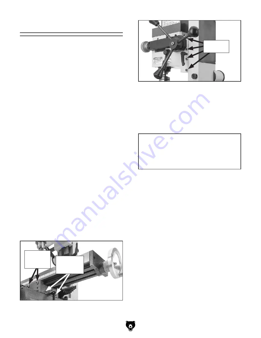
3. Loosen hex nuts on gib screws along desired
gib adjustment (see
Figure 38).
4. Loosen set screws and move sliding device
back-and-forth to make sure gibs are loose,
then tighten set screws until you feel light
resistance in the handwheel.
5. Use hex wrench to prevent set screws from
moving, then re-tighten hex nuts to secure
the setting.
6. Re-check movement of slide and, if neces-
sary, repeat
Steps 3–5.
Figure 39. Location of Z-Axis gib screws.
Z-Axis Gib
Screws
NOTICE
Excessively loose gibs may cause poor
workpiece finishes. Excessively tight gibs
may cause premature wear of sliding sur-
faces and ways.
Figure 38. Location of gib adjustment set
screws.
Y-Axis Set
Screws
(2 of 3)
X-Axis Set
Screws and
Hex Nuts
Summary of Contents for G0781
Page 52: ......


