-4-
Model G0765 (Mfd. Since 5/15)
Controls &
Components
Refer to
Figures 2–6 and the following descrip-
tions to become familiar with the basic controls of
this lathe.
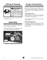
To reduce your risk of
serious injury, read this
entire manual BEFORE
using machine.
Control Panel
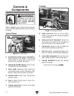
Figure 2. Control panel.
B
A
C
F
E
A. On/Off Switch w/Emergency Stop Button:
When pressed, cuts power to motor and
control panel. To reset, press in side tab, lift
switch cover, and press On button.
B. Spindle Speed RPM Display: Shows a digi-
tal readout of the spindle speed.
C. Power Light: Illuminates when machine is
connected to power source, Emergency Stop
Button is reset, and On button is pressed.
D. Spindle Switch: Starts, stops, and reverses
spindle rotation.
E. Fuse: Protects control panel in case of an
electrical overload.
F. Variable Speed Dial: Controls the variable
speed of the spindle.
Carriage
G. 4-Way Tool Post: Holds up to four cutting
tools at once that can be individually indexed
to the workpiece.
H. Compound Rest Handwheel: Moves the
tool toward and away from the workpiece at
the preset angle of the compound rest.
I. Thread Dial: Indicates when to engage the
half nut during threading operations.
J. Half Nut Lever: Engages/disengages half
nut for power feed and threading operations.
K. Cross Slide Handwheel: Moves the cross
slide toward and away from the workpiece.
L. Carriage Handwheel: Moves the carriage
along the bedway.
Figure 3. Carriage controls.
G
H
I
K
L
J
D
Summary of Contents for G0765
Page 76: ......


