background image

-52-

Model G0765 (Mfd. Since 5/15)

SECTION 7: SERVICE

Troubleshooting

Symptom

Possible Cause

Possible Solution

Machine does not 
start or a circuit 
breaker trips.

1.  Emergency stop button engaged or at fault.

2.  Variable speed dial in OFF position or at 

fault.

3.  Spindle direction switch turned to "0" or at 

fault.

4.  Blown fuse.
5.   Incorrect power supply voltage.
6.  Power supply circuit breaker tripped or fuse 

blown.

7.  Wiring open/has high resistance.
8.  Motor brushes at fault.
9.  On/Off switch at fault.
10. Motor at fault.

1.  Press side tab in and lift switch cover. Press On 

button to reset; replace if not working properly.

2.  Turn variable speed dial past "0". Ensure dial has 

correct voltage. Replace if faulty.

3.  Turn spindle direction switch to "F" or "R". Ensure 

dial has correct voltage. Replace if faulty. 

4.  Replace fuse/ensure no shorts (

Page 58).

5.  Ensure correct power supply voltage.
6.  Ensure circuit is sized correctly and free of shorts. 

Reset circuit breaker or replace fuse.

7.  Check/fix broken, disconnected, or corroded wires. 
8.  Remove/replace brushes (

Page 59).

9.  Replace switch.
10. Test/repair/replace.

Machine stalls or is 
underpowered.

1.  Feed rate/cutting speed too fast.
2.  Wrong workpiece material.
3.  Machine undersized for task.
4.  Motor overheated.
5.  Computer board at fault.
6.  Motor speed dial at fault.
7.  Timing belt slipping.
8.  Motor brushes at fault.
9.  Pulley/sprocket slipping on shaft.
10. Motor bearings at fault.
11. Motor at fault.

1.  Decrease feed rate/cutting speed.
2.  Use correct type/size of metal.
3.  Inspect and replace if at fault.
4.  Use sharp bits; reduce feed rate/depth of cut.
5.  Clean motor, let cool, and reduce workload.
6.  Test and replace if at fault.
7.  Tension/replace belt; ensure pulleys are aligned.
8.  Remove/replace brushes (

Page 59).

9.  Replace loose pulley/shaft.
10. Test/repair/replace.
11. Test/repair/replace.

Machine has 
vibration or noisy 
operation.

1.  Motor or component loose.

2.  Pulley loose.
3.  Motor fan rubbing on fan cover.
4.  Motor bearings at fault.

5.  Cutting tool chattering.

6.  Workpiece or chuck at fault.

1.  Inspect/replace damaged bolts/nuts, and retighten 

with thread locking fluid.

2.  Realign/replace shaft, pulley, setscrew, and key.
3.  Fix/replace fan cover; replace loose/damaged fan.
4.  Test by rotating shaft; rotational grinding/loose shaft 

requires bearing replacement.

5.  Replace/sharpen cutting tool; index tool to spindle 

centerline; use correct feed rate and cutting RPM.

6.  Properly secure or center workpiece in chuck or 

faceplate; replace defective chuck.

Review  the  troubleshooting  and  procedures  in  this  section  if  a  problem  develops  with  your  machine.  If 
you need replacement parts or additional help with a procedure, call our Technical Support. 

Note: Please 

gather the serial number and manufacture date of your machine before calling.

Summary of Contents for G0765

Page 1: ...manufactured since 5 15 COPYRIGHT MARCH 2014 BY GRIZZLY INDUSTRIAL INC REVISED FEBRUARY 2018 HE WARNING NO PORTION OF THIS MANUAL MAY BE REPRODUCED IN ANY SHAPE OR FORM WITHOUT THE WRITTEN APPROVAL OF GRIZZLY INDUSTRIAL INC BLTSDM16229 PRINTED IN CHINA V2 02 18 ...

Page 2: ...ng grinding tool integrity and the usage of personal protective equipment The manufacturer will not be held liable for injury or property damage from negligence improper training machine modifications or misuse Some dust created by power sanding sawing grinding drilling and other construction activities contains chemicals known to the State of California to cause cancer birth defects or other repr...

Page 3: ...n 24 Scroll Chuck Clamping 25 Changing Jaw Set 25 Faceplate 27 Tailstock 28 Centers 32 Steady Rest 34 Compound Rest 35 Four Way Tool Post 35 Manual Feed 37 Spindle Speed 37 Power Feed 39 End Gears 41 Threading 44 SECTION 5 ACCESSORIES 47 SECTION 6 MAINTENANCE 48 Schedule 48 Cleaning Protecting 48 Lubrication 49 Machine Storage 51 SECTION 7 SERVICE 52 Troubleshooting 52 Backlash Adjustment 54 Leads...

Page 4: ... com We want your feedback on this manual What did you like about it Where could it be improved Please take a few minutes to give us feedback Grizzly Documentation Manager P O Box 2069 Bellingham WA 98227 2069 Email manuals grizzly com Contact Info We are proud to provide a high quality owner s manual with your new machine We made every effort to be exact with the instruc tions specifications draw...

Page 5: ...ch U Fuse V Variable Speed Dial W End Cover Serious personal injury could occur if you connect the machine to power before completing the setup process DO NOT connect power until instructed to do so later in this manual Untrained users have an increased risk of seriously injuring themselves with this machine Do not operate this machine until you have understood this entire manual and received prop...

Page 6: ...utton is reset and On button is pressed D Spindle Switch Starts stops and reverses spindle rotation E Fuse Protects control panel in case of an electrical overload F Variable Speed Dial Controls the variable speed of the spindle Carriage G 4 Way Tool Post Holds up to four cutting tools at once that can be individually indexed to the workpiece H Compound Rest Handwheel Moves the tool toward and awa...

Page 7: ...stance of tailstock offset from spindle centerline S Tailstock Offset Screws Adjusts tailstock offset left or right from spindle centerline 1 of 2 R S T High Low Range Lever Sets the spindle speed range to LOW 100 1000 RPM or HIGH 100 2000 RPM Do NOT shift while lathe is running or damage to machine may occur U Feed Direction Lever Used to select leadscrew rotation direction Up is for clock wise r...

Page 8: ...ntent Machine Weight 110 lbs Length x Width x Height 33 x 15 x 15 in Must Ship Upright Yes Electrical Power Requirement 110V Single Phase 60 Hz Full Load Current Rating 10A Minimum Circuit Size 15A Connection Type Cord Plug Power Cord Included Yes Power Cord Length 6 ft Power Cord Gauge 18 AWG Plug Included Yes Included Plug Type NEMA 5 15 Switch Type ON OFF Push Button Switch w Safety Cover Motor...

Page 9: ...k Taper MT 2 Tailstock Barrel Diameter 0 870 in Threading Info Number of Longitudinal Feeds 1 Range of Longitudinal Feeds 0 004 in rev Number of Inch Threads 18 Range of Inch Threads 12 52 TPI Number of Metric Threads 10 Range of Metric Threads 0 4 2 mm Dimensions Bed Width 3 1 4 in Carriage Leadscrew Diameter 5 8 in Leadscrew TPI 16 TPI Carriage Leadscrew Length 19 3 4 in Steady Rest Capacity 2 i...

Page 10: ...proof DANGEROUS ENVIRONMENTS Do not use machinery in areas that are wet cluttered or have poor lighting Operating machinery in these areas greatly increases the risk of accidents and injury MENTAL ALERTNESS REQUIRED Full mental alertness is required for safe operation of machin ery Never operate under the influence of drugs or alcohol when tired or when distracted For Your Own Safety Read Instruct...

Page 11: ...moving parts or flying debris Make sure they are properly installed undamaged and working correctly BEFORE operating machine FORCING MACHINERY Do not force machine It will do the job safer and better at the rate for which it was designed NEVER STAND ON MACHINE Serious injury may occur if machine is tipped or if the cutting tool is unintentionally contacted STABLE MACHINE Unexpected movement dur in...

Page 12: ...STOCK SAFETY Long stock can whip violently if not properly supported Always support any stock that extends from the chuck headstock more than three times its own diameter CLEARING CHIPS Metal chips can be razor sharp Avoid clearing them by hand or with a rag Use a brush or vacuum instead SECURE WORKPIECE An improperly secured workpiece can fly off spindle with deadly force Make sure workpiece is p...

Page 13: ...ce To reduce the risk of this haz ard read and understand this document and seek additional training from an experienced chuck user before using a chuck CHUCK CAPACITY Avoid exceeding the capacity of the chuck by clamping an oversized workpiece If the workpiece is too large to safely clamp with the chuck use a faceplate or a larger chuck if pos sible Otherwise the workpiece could be thrown from th...

Page 14: ...cuit To reduce the risk of these hazards avoid over loading the machine during operation and make sure it is connected to a power supply circuit that meets the specified circuit requirements For your own safety and protection of property consult an electrician if you are unsure about wiring practices or electrical codes in your area Note Circuit requirements in this manual apply to a dedicated cir...

Page 15: ...rd size gets longer and the gauge size gets smaller higher gauge numbers indicate smaller sizes Any extension cord used with this machine must be in good condition and contain a ground wire and matching plug receptacle Additionally it must meet the following size requirements Minimum Gauge Size 14 AWG Maximum Length Shorter is Better 50 ft Grounding Plug Requirements Figure 7 Typical 5 15 plug and...

Page 16: ...pets away from plastic bags or packing materials shipped with this machine Discard immediately The following are needed to complete the setup process but are not included with your machine Description Qty Additional People 1 Safety Glasses 1 For Each Person Cleaner Degreaser Page 18 As Needed Quality Metal Protectant As Needed Disposable Shop Rags As Needed Needed for Setup This machine was carefu...

Page 17: ...il 1 K 3 Jaw Chuck External Jaw Set 1 L Dead Center MT 3 1 M Dead Center MT 2 1 N Fuse 1 O Cross Slide Handwheel Handle 1 P Carriage Handwheel Handle 1 Q 3 Jaw Chuck Key 1 R Change Gear Set 1 Change Gear 20 tooth Installed 1 Change Gear 30 tooth 1 Change Gear 35 tooth 1 Change Gear 40 tooth 2 Change Gear 45 tooth 1 Change Gear 50 tooth 1 Change Gear 55 tooth 1 Figure 8 Installed components D A B C...

Page 18: ...c paint scraper optional Basic steps for removing rust preventative 1 Put on safety glasses 2 Coat the rust preventative with a liberal amount of cleaner degreaser then let it soak for 5 10 minutes 3 Wipe off the surfaces If your cleaner degreas er is effective the rust preventative will wipe off easily If you have a plastic paint scraper scrape off as much as you can first then wipe off the rest ...

Page 19: ... below for required space allocation Physical Environment The physical environment where the machine is operated is important for safe operation and lon gevity of machine components For best results operate this machine in a dry environment that is free from excessive moisture hazardous chemi cals airborne abrasives or extreme conditions Extreme conditions for this type of machinery are generally ...

Page 20: ... installed properly Connecting Power Always make sure the spindle dial on the head stock is turned to 0 rotated fully counterclock wise before connecting power Insert the power cord plug into a matching power supply receptacle Disconnecting Power If you need to disconnect the machine from power for maintenance service or adjustments turn the machine OFF and pull the plug completely out of the rece...

Page 21: ...from using this machine BEFORE understanding its controls and related safety information DO NOT operate or allow others to operate machine until the information is understood To test run machine 1 Set spindle direction switch to neutral 0 position and turn variable speed dial all the way counterclockwise to 0 High Low Range Lever Feed Direction Lever DOWN CCW Rotation UP Clockwise Rotation CENTER ...

Page 22: ...s 100 RPM The spindle should rotate counterclockwise down and toward the front of the lathe 7 Push Emergency Stop button to turn lathe OFF Then without resetting Emergency Stop button try to restart spindle rotation by turning variable speed dial all the way coun terclockwise to 0 and then clockwise The spindle should not start If spindle does start with Emergency Stop button pressed in the button...

Page 23: ...ndle bearings and other precision components by thoroughly lubricating them before placing them under load After spindle break in is complete we recommend changing headstock and gearbox oil to remove any metal particles or debris that are present from the assembly and break in process The break in must be performed in succession with the Test Run procedure described in this manual as the steps in ...

Page 24: ...hed turning rotates variable speed dial to 0 to stop spindle presses Emergency Stop button then removes workpiece The purpose of this overview is to provide the nov ice machine operator with a basic understanding of how the machine is used during operation so the machine controls components discussed later in this manual are easier to understand Due to the generic nature of this overview it is not...

Page 25: ...ich are used for square or unevenly shaped stock and to mount work that needs to be adjusted to near zero total indicated runout The included faceplate has slots for T bolts that hold standard or custom clamping hardware With the correct clamping hardware a faceplate offers a wide range of uses including machining non concentric workpieces straight turning between centers off center turning and bo...

Page 26: ...e nose and chuck mating surfaces are clean Even a small amount of lint or debris can affect accuracy The chuck is properly installed when it is seated against the backplate shoulder see Figure 19 below To install the chuck 1 DISCONNECT LATHE FROM POWER 2 Use an appropriate device to protect ways dur ing installation process refer to Installation Removal Device on Page 25 3 Thoroughly clean and wip...

Page 27: ...rip Unstable Workpiece Shallow Bar Stock Shallow Bar Stock Safer Outside Jaw Use Safer Inside Jaw Use CORRECT CORRECT CORRECT CORRECT INCORRECT INCORRECT INCORRECT INCORRECT Scroll Chuck Clamping Figure 22 Jaw selection and workpiece holding Changing Jaw Set The 3 jaw scroll chuck included with the lathe features inside and outside hardened steel jaw sets see Figure below which move in unison to c...

Page 28: ...ee from moisture and abrasives 6 Rotate chuck key clockwise until you see tip of outer scroll gear lead thread about to enter a jaw guide see below Lead Thread 1 Figure 25 Lead thread on scroll gear 7 Insert jaw 1 into jaw guide and hold jaw against scroll gear 8 Rotate chuck key clockwise one turn to engage tip of scroll gear lead thread into jaw Pull jaw it should be locked into jaw guide 9 Inst...

Page 29: ...assem bly and use a dial indicator to make sure workpiece is properly positioned for your operation Faceplate Failure to properly secure workpiece to faceplate could cause workpiece to be thrown from lathe with deadly force To reduce this risk use a minimum of THREE independent clamping devices to hold workpiece onto faceplate Machining non concentric workpieces at high speeds could cause workpiec...

Page 30: ...set from the spindle center for tapered turning The tailstock quill also features independent adjustment controls that allow it to be advanced toward the spindle or locked firmly in position Graduated Dial on Handwheel Increments 0 001 One Full Revolution 0 200 Increments on Quill Scale Inch 0 2 in 1 8 Increments Metric 0 50mm in 1mm Increments Tailstock Quill Specs Positioning Tailstock 1 Rotate ...

Page 31: ...e end then a screw can be threaded into the end of the tool to provide a solid surface for the quill pin to push against when the quill is retracted for tool removal Otherwise removal of such tooling may be difficult Offsetting Tailstock The tailstock quill can be offset from the spindle centerline for turning tapers Offsetting the quill toward the front of the lathe results in a taper at the tail...

Page 32: ...erline Figure 32 Turning a dead center This is an essential adjustment that should be ver ified or performed each time the tailstock is used to turn concentric workpieces between centers or immediately after offsetting the tailstock when turning a taper If the tailstock is not aligned with the spindle centerline when it is supposed to be turning results will be inaccurate along the length of the w...

Page 33: ... as shown in Figure below If test stock is thinner at tailstock end move tailstock toward back of lathe 1 2 the distance of taper amount as shown below Looking down from above Move tailstock toward back of lathe 1 2 the amount of taper Figure 35 Adjust tailstock away from the operator 8 Repeat Steps 5 7 until desired accuracy is achieved Figure 33 Example of stock mounted between the centers 5 Tur...

Page 34: ...ed in spindle using a lathe dog and faceplate for turning between centers Dead Centers Dead centers are one piece high speed steel centers that require low spindle speeds and a small amount of oil to reduce friction heat that may damage the workpiece Mount the MT 2 dead center see Figure 36 in the tailstock Since the workpiece will rotate against the center and generate friction the tip of the cen...

Page 35: ...asting until the center releases If the center does not come loose by retracting the quill extend the quill to expose the slot shown in the Figure below then use a drift key to remove the center Mounting Workpiece Between Centers 1 DISCONNECT LATHE FROM POWER 2 Drillcenterholesinbothendsoftheworkpiece 3 Install MT 3 dead center in spindle with lathe dog and chuck or faceplate then install live cen...

Page 36: ...ER 2 Thoroughly clean all mating surfaces then place steady rest base on bedways 3 Loosen finger lock nuts see Figure 40 turn finger adjustment knobs and adjust fingers as required for workpiece 4 Loosen steady rest lock nut position steady rest where required to properly support workpiece then secure lock nut 5 Turn finger adjustment knobs so fingers barely touch workpiece then tighten finger loc...

Page 37: ...stments Cap Screws Angle Scale Four Way Tool Post Tool Needed Qty Hex Wrench 5mm 1 Installing Tool Figure 42 Example of tool mounted in tool post Cutting Tool Tool Post Screw The four way tool post is mounted on top of the compound rest and allows a maximum of four tools to be loaded simultaneously Each tool can be quickly indexed to the workpiece by loosening the top handle rotating the tool post...

Page 38: ...nter Align the tip of the cutting tool with a tailstock center as instructed in the following pro cedure For this to work the tailstock must be aligned to the spindle centerline refer to Aligning Tailstock To Spindle Centerline for detailed instructions Cutting Tool Spindle Center Line Figure 43 Cutting tool aligned with spindle centerline viewed from tailstock Tools Needed Qty Hex Wrench 6mm 1 St...

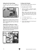
Page 39: ...lts as well as maximizing tool life To set the spindle speed for your operation you will need to 1 Determine the best spindle speed for the cutting task and 2 configure the lathe controls to produce the required spindle speed Determining Spindle Speed Many variables affect the optimum spindle speed to use for any given operation but the two most important are the recommended cutting speed for the ...

Page 40: ...e speed dis plays on the spindle speed display Configuration Example Follow this example to gain a better understand ing of how to set the spindle speed To set spindle speed to 100 RPM 1 Make sure spindle is completely stopped and shift high low range lever to LOW as shown in Figure 47 Note If high low range lever does not eas ily adjust into position rotate chuck by hand while you apply pressure ...

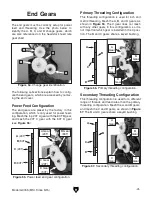
Page 41: ...e is completely stopped BEFORE using headstock controls to make changes Power Feed Controls Use the following descriptions and figures to understand the power feed controls Before using power feed you may have to recon figure the end gears depending on how they are set up The lathe comes from the factory with the end gears setup in the standard configuration refer to End Gears on Page 43 This end ...

Page 42: ...ate 8 Reposition adjuster so gears mesh tighten adjuster hex nut then secure gears with cap screws and flat washers removed earlier 9 Re install end cover 10 Push half nut lever down to engage power feed see Figure 53 Figure 53 Half nut lever engaged Half Nut Lever The lathe is now set for a power feed rate of 0 04 in rev Engaged Halfnut Lever Disengaged 6 Remove existing A B C and D change gears ...

Page 43: ...tion This threading configuration is used for a different range of threads and feed rates than the primary threading configuration Mesh the A and B gears and mesh the C and D gears as shown in Figure 57 The B and C gears share a keyed bushing Figure 57 Secondary threading configuration A 20T B 80T D 80T C 20T A B C D B A C D C Gear B Gear A Gear C Gear D Gear D Gear Power Feed Configuration The en...

Page 44: ...ear Setup TPI Gear Setup 12 13 14 16 18 19 20 22 24 A B C D A B C D 40 30 26 40 60 65 40 30 35 40 45 57 50 55 60 60 40 40 40 40 40 40 40 50 65 65 65 65 65 65 65 65 65 65 65 65 65 65 60 60 28 32 36 38 40 44 48 52 20 20 20 20 20 20 20 20 50 60 35 40 45 57 50 55 60 65 C Gear 40T Gear 65T Gear 50T Gear 20 TPI Figure 59 B C change gear and keyed bushing gears removed for clarity C Gear B Gear Keyed Bus...

Page 45: ...gears mesh Then tight en adjuster hex nut and B C gear shaft hex nut 14 Secure gears with cap screws and washers removed earlier 15 Re install end cover 9 Remove existing B gear from keyed bushing shared with C gear 10 Slide 65T B gear onto keyed bushing and firmly against C gear Figure 62 D gear shaft key and bushing Key Bushing 11 Slide 40T 65T and 50T gears onto gear shafts see Figure 63 making...

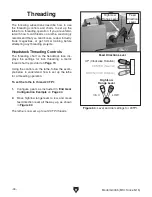
Page 46: ... for inch threading a metric thread chart is provided on Page 70 Using the controls on the lathe follow the exam ple below to understand how to set up the lathe for a threading operation To set the lathe to thread 20 TPI 1 Configure gears as instructed in End Gear Configuration Example on Page 44 2 Move high low range lever to low and move feed direction lever all the way up as shown in Figure 64 ...

Page 47: ...dscrew which moves the carriage and cutting tool along the length of the workpiece for thread ing operations see Figure 65 Figure 65 Apron threading controls Engaged Halfnut Lever Disengaged Half Nut Lever Thread Dial Thread Dial Chart The thread dial chart is located on the headstock as shown in Figure 66 TPI Scale TPI Scale Thread Dial Chart 12 13 14 16 18 19 20 22 24 1 3 5 7 1 1 5 1 8 1 5 1 1 3...

Page 48: ...9 Figure 71 Example of odd numbered inch thread pitch 7 1 3 5 Thread Dial TPI Dial Number 1 3 5 7 12 20 28 36 44 52 Figure 69 Example of inch thread pitch divisible by 4 Even TPI Divisible by 4 Use any numbered line on thread dial see example in Figure 69 The following examples explain how to use the thread dial and the thread dial chart TPI Divisible by 8 Use any line on the thread dial see examp...

Page 49: ... was designed to answer customer requests for a slightly wider and taller table than our D2056 to accommodate a variety of bench top machines Figure 73 D3640 Shop Fox Tool Table Plus T25206 11 Pc Carbide Bit Set 5 16 This 11 Pc Carbide Tipped Tool Bit Set includes a wide variety of tool types for just about any machining operation This set also includes two boring bars Boring bars measure 47 8 lon...

Page 50: ...from bed slides Wipe down all unpainted or machined sur faces with an oiled rag Annually Lubricate change gear bushing and tumbler gears Page 53 Cleaning Protecting Because of its importance we recommend that the cleaning routine be planned into the workflow schedule Typically the easiest way to clean swarf from the machine is to use a wet dry shop vacuum that is dedicated for this purpose The sma...

Page 51: ...with a pump type oil can that has a plastic or rubber ized cone tip We do not recommend using metal needle or lance tips as they can push the ball too far into the oiler break the spring seat and lodge the ball in the oil galley Lubricate the ball oilers before and after machine use and more frequently under heavy use When lubricating ball oilers first clean the outside sur face to remove any dust...

Page 52: ...unt As Needed Lubrication Frequency Daily Before lubricating the bedways see Figure 76 clean them with mineral spirits Apply a thin coat of oil along the length of the bedways Move the steady rest carriage and tailstock to access the entire length of the bedways Cross Slide Compound Slide Oil Type Grizzly SB1365 or ISO 68 Equivalent Amount Thin Coat Lubrication Frequency Daily Use the handwheels t...

Page 53: ... ered but that the rust preventative or grease is kept off of painted surfaces 3 Lubricate machine as outlined in lubrication section Be sure to use an oil can to purge all ball oilers and oil passages with fresh oil 4 Place a few moisture absorbing desiccant packs inside of the electrical box 5 Cover lathe and place it in a dry area that is out of direct sunlight and away from hazard ous fumes pa...

Page 54: ...peed dial at fault 7 Timing belt slipping 8 Motor brushes at fault 9 Pulley sprocket slipping on shaft 10 Motor bearings at fault 11 Motor at fault 1 Decrease feed rate cutting speed 2 Use correct type size of metal 3 Inspect and replace if at fault 4 Use sharp bits reduce feed rate depth of cut 5 Clean motor let cool and reduce workload 6 Test and replace if at fault 7 Tension replace belt ensure...

Page 55: ...lash to a minimum see Page 56 4 Adjust leadscrew to remove end play see Page 56 Cross slide compound or carriage handwheels hard to move 1 Ways loaded with chips dust or grime 2 Gibs are too tight 3 Backlash setting too tight 4 Bedways are dry 5 Half nut lever engaged 1 Clean ways and lubricate 2 Loosen gibs slightly see Page 57 3 Slightly loosen backlash setting see Page 56 4 Lubricate bedways 5 ...

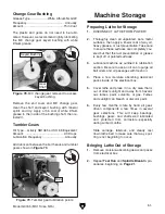
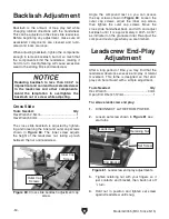
Page 56: ...of the leadscrew nut taking up lash between the nut and leadscrew Angle the compound rest so you can access the cap screws shown in Figure 80 Loosen the outer cap screws adjust the inner cap screw then tighten the outer cap screws Move the cross slide handwheel back and forth and adjust backlash until it is approximately 0 002 0 003 as indicated on the graduated dial Re adjust the compound rest an...

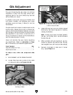
Page 57: ...ovement of slide and if neces sary repeat Steps 2 4 Figure 83 Compound slide gib adjustment hex nuts and cap screws The gib adjustment process usually requires some trial and error Repeat the process as necessary until you find the best balance between loose and stiff movement Most machinists find that the ideal gib adjustment is one where a small amount of drag or resistance is present yet the ha...

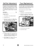
Page 58: ... This lathe features an on board fuse designed to blow to protect sensitive electrical parts from thermal damage in the event of an overload If the spindle does not start replace the fuse Replacement fuse part number P0765166 To replace fuse 1 DISCONNECT LATHE FROM POWER 2 Unthread fuse holder by rotating counter clockwise see Figure 85 and remove fuse 4 Engage disengage half nut several times and...

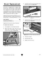
Page 59: ...han 1 4 long new brushes are 5 8 long Tools Needed Qty Flat Head Screwdriver 2 1 Phillips Head Screwdriver 2 1 Replacement brush part number P0765150 1 Cap 3 Unscrew rear brush cap and carefully remove brush from motor see Figure 87 To replace motor brushes 1 DISCONNECT LATHE FROM POWER 2 Remove the three screws that secure rear motor cover then remove cover to gain access to rear brush see Figure...

Page 60: ...ccess timing belt 3 Verify belt is centered on drive pulley see Figure 89 by hand rotating chuck The belt should be seated so it does not contact head stock or hang out at end of pulley If belt is not centered loosen motor mount hex nuts see Figure 89 re adjust motor position and re tension belt 4 Loosen both motor mount hex nuts 5 Ensure belt teeth are properly engaged in pulley notches push down...

Page 61: ... outer spanner nut speed sensor and sensor wheel 5 Remove side cover assembly 6 Loosen motor mount hex nuts shown in Figure 92 Speed Sensor Side Cover Outer Spanner Nut 8 Tension timing belt Refer to Tensioning Timing Belt on Page 60 for detailed instruc tions 9 Check alignment marks you made on inner spanner nut and gear in Step 3 The marks should still be aligned If marks are not aligned adjust ...

Page 62: ... but may not match your machine If you find this to be the case use the wiring diagram inside the motor junction box CAPACITORS INVERTERS Some capacitors and power inverters store an electrical charge for up to 10 minutes after being disconnected from the power source To reduce the risk of being shocked wait at least this long before working on capacitors EXPERIENCING DIFFICULTIES If you are expe ...

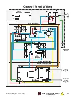
Page 63: ...ide From Behind KEDU ZHA Right Side From Behind DIRECTION SWITCH DIRECTION SWITCH POWER LAMP 10 7 1 5 9 2 6 3 8 4 12 11 T 11 12 P1 P3 P2 A L2 A L1 4 3 2 1 3 2 1 24 24 24 23 13 14 14 14 14 P1 P1 P2 P2 P3 P3 12 12 11 11 7 7 9 9 5 5 10 10 10 6 A L2 L2 2 A 12 12 L1 L1 L2 L2 JD 014 REV A 09111 CIRCUIT BOARD KSP CIRCUIT BOARD FUSE VARIABLE SPEED GND To Plug Page 65 To Speed Sensor Page 65 To Motor Page ...

Page 64: ...Mfd Since 5 15 READ ELECTRICAL SAFETY ON PAGE 62 Control Panel Wiring Photos Figure 96 Control panel wiring top Figure 94 G0765 wiring overview Figure 97 Control panel wiring front Figure 95 Control panel wiring bottom ...

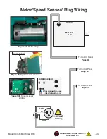
Page 65: ...10 VAC 5 15 Plug SPEED SENSOR 83ZYT007 110V Wires connect on back side of circuit board To Control Panel Page 63 To Control Panel Page 63 To Control Panel Page 63 Figure 100 Speed sensor wiring Figure 98 Motor wiring Figure 99 Speed sensor location Motor Speed Sensor Plug Wiring Speed Sensor ...

Page 66: ...3 84 85 86 87 88 89 90 91 92 93 94 95 96 97 98 98 99 99 100 101 102 105 106 107 108 109 110 111 112 113 114 115 116 117 119 123 124 125 126 127 128 129 131 133 134 135 136 137 138 139 140 141 142 143 144 145 146 148 150 150 1 150 2 151 152 153 157 158 159 160 161 162 163 164 165 166 167 168 169 170 171 174 175 176 177 178 179 180 181 182 183 184 185 186 187 188 189 190 191 192 193 194 52 83 67 67 ...

Page 67: ...L SHAFT 83 P0765083 SET SCREW M6 1 X 12 27 P0765027 SPINDLE PULLEY 84 P0765084 HANDWHEEL 28 P0765028 EXT RETAINING RING 10MM 85 P0765085 HANDWHEEL HANDLE M5 8 X 6 29 P0765029 TIMING BELT 1 5M 70 9 5 86 P0765086 CROSS BALL HANDLE 2 PC 30 P0765030 SHIFTING FORK 87 P0765087 GRADUATED DIAL 31 P0765031 SHIFTING ARM 88 P0765088 CROSS LEADSCREW BRACKET 32 P0765032 H L LEVER HUB 89 P0765089 CROSS LEADSCRE...

Page 68: ...72 DEAD CENTER MT 3 131 P0765131 LEADSCREW END BRACKET 174 P0765174 FACEPLATE 5 133 P0765133 CAP SCREW M3 5 X 10 175 P0765175 LATHE CHUCK KEY 3 8 STD 134 P0765134 RACK 176 P0765176 EXTERNAL JAWS 3 PC SET 135 P0765135 TAILSTOCK CLAMP PLATE 177 P0765177 HEX WRENCH 2 5MM 136 P0765136 FLAT WASHER 10MM 178 P0765178 HEX WRENCH 3MM 137 P0765137 SET SCREW M5 8 X 16 179 P0765179 HEX WRENCH 4MM 138 P0765138...

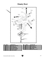
Page 69: ...0765173 1 HEX NUT M8 1 25 173 7 P0765173 7 HEX NUT M8 1 25 173 2 P0765173 2 LOCK WASHER 8MM 173 8 P0765173 8 FLAT WASHER 8MM 173 3 P0765173 3 STEADY REST CASTING 173 9 P0765173 9 BASE CLAMP 173 4 P0765173 4 STEADY REST FINGER 173 10 P0765173 10 HEX BOLT M8 1 25 X 45 173 5 P0765173 5 ADJUSTING SCREW 173 173 1 173 2 173 3 173 4 173 5 173 6 173 7 173 8 173 9 173 10 ...

Page 70: ...0765257 DRO LABEL 252 P0765252 THREAD DIAL CHART LABEL 258 P0765258 SPINDLE SPEED WARNING LABEL 253 P0765253 READ MANUAL LABEL 259 P0765259 GRIZZLY GREEN TOUCH UP PAINT 254 P0765254 GLASSES FACE SHIELD WARNING LABEL 260 P0765260 HALF NUT LEVER LABEL 255 P0765255 CHANGE DIRECTION NOTICE LABEL 261 P0765261 DISCONNECT POWER WARNING LABEL 256 P0765256 ENTANGLEMENT WARNING LABEL ...

Page 71: ...ST replace it in the original location before resuming operations For replacements contact 800 523 4777 or www grizzly com REF PART DESCRIPTION REF PART DESCRIPTION 254 P0765254 GLASSES FACE SHIELD WARNING LABEL 263 P0765263 OUTBOARD ENTANGLE WARNING LABEL 255 P0765255 CHANGE DIRECTION NOTICE LABEL 264 P0765264 THREAD CHART LABEL 256 P0765256 ENTANGLEMENT WARNING LABEL 265 P0765265 ELECTRICITY LAB...

Page 72: ...5 30 26 40 60 65 13 40 65 60 30 28 20 65 35 14 40 65 35 32 20 65 40 16 40 65 40 36 20 65 45 18 40 65 45 38 20 50 60 57 19 40 50 60 57 40 20 65 50 20 40 65 50 44 20 65 55 22 40 65 55 48 20 65 60 24 40 65 60 52 20 60 65 Figure 101 Threads per inch chart TPI mm pitch Gear A B C D 0 4 20 57 40 55 0 5 20 57 45 50 0 6 20 60 57 50 0 7 30 45 40 60 0 8 40 55 35 50 1 0 30 60 57 45 1 25 45 40 35 50 1 5 65 40...

Page 73: ... metalworker ____ 0 2 Years ____ 2 8 Years ____ 8 20 Years ____20 Years 6 How many of your machines or tools are Grizzly ____ 0 2 ____ 3 5 ____ 6 9 ____10 7 Do you think your machine represents a good value _____Yes _____No 8 Would you recommend Grizzly Industrial to a friend _____Yes _____No 9 Would you allow us to use your name as a reference for Grizzly customers in your area Note We never use ...

Page 74: ...D LINE FOLD ALONG DOTTED LINE GRIZZLY INDUSTRIAL INC P O BOX 2069 BELLINGHAM WA 98227 2069 Place Stamp Here Name_______________________________ Street_______________________________ City______________State______Zip______ Send a Grizzly Catalog to a friend ...

Page 75: ... shall be tried in the State of Washington County of Whatcom We shall in no event be liable for death injuries to persons or property or for incidental contingent special or consequential damages arising from the use of our products To take advantage of this warranty contact us by mail or phone and give us all the details We will then issue you a Return Number which must be clearly posted on the o...

Page 76: ......
Reviews: