background image

-50-

Model G0705 (Mfg. since 09/09)

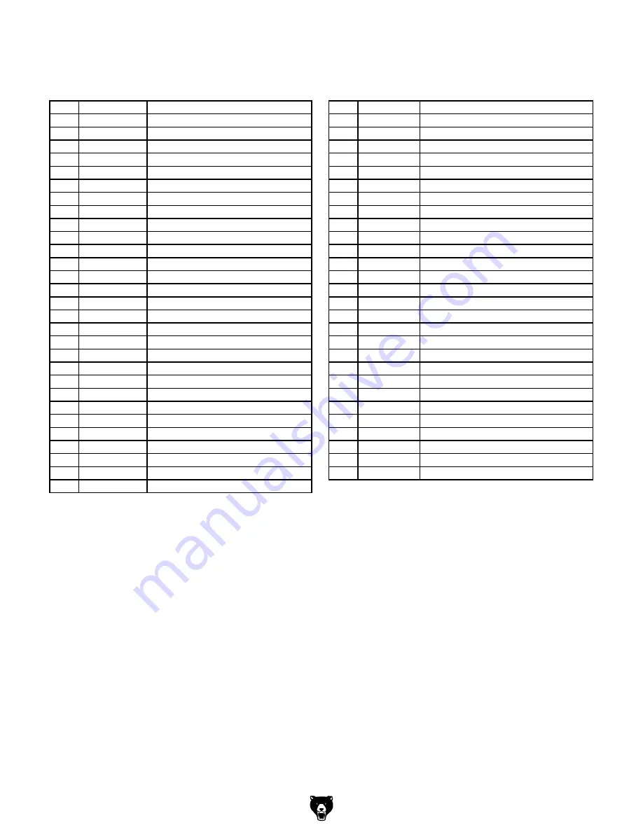
headstock parts list (continued)

REF PART #

DESCRIPTION

REF PART #

DESCRIPTION

48

PCAP05

CAP SCREW 1/4-20 X 3/4

80

P0705080

PULLEY IDLER PLATE

49

P0705049

ELEVATION CRANK

81

PN04

HEX NUT 5/8-11

51

P0705051

CLAMP HANDLE

82

PW07

FLAT WASHER 5/16

52

P0705052

OUTER QUILL CLAMP

83

PCAP08

CAP SCREW 5/16-18 X 1-1/2

53

P0705053

INNER QUILL CLAMP

84

P0705084

IDLER PULLEY

54

P0705054

QUILL CLAMP SPACER

85

PN04

HEX NUT 5/8-11

55

P0705055

QUILL CLAMP HANDLE

86

P0705086

MOTOR PULLEY SET

56

P0705056

SCREW KEY

88

PVA33

V-BELT A33

57

PN08

HEX NUT 3/8-16

89

PVA39

V-BELT A39

58

P0705058

COMPRESSION SPRING

90

P0705090

WIRE CLIP

59

P0705059

BELT TENSION PIN

91

PCAP09

CAP SCREW 5/16-18 X 5/8

60

P0705060

RUBBER PAD

92

P0705092

MOTOR MOUNT PLATE

61

PB46

HEX BOLT 5/8-11 X 6

93

P0705093

MOTOR 2HP 110/220V 1-PH

62

PW14

FLAT WASHER 5/8

93-1

P0705093-1

MOTOR JUNCTION BOX

63

PN04

HEX NUT 5/8-11

93-2

PC150D

S CAPACITOR 150M 250V 1-5/8 X 3-1/4

64

P0705064

HEADSTOCK WRENCH

93-3

PC20B

R CAPACITOR 20M 450V 1-5/8 X 3-1/4

65

P0705065

LOCK HANDLE M8-1.25 X 25

93-4

P0705093-4

MOTOR FAN

66

P0705066

FRONT COVER PLATE ASSEMBLY

93-5

P0705093-5

MOTOR FAN COVER

67

PCAP04

CAP SCREW 1/4-20 X 1/2

94

PW07

FLAT WASHER 5/16

68

P0705068

LIMIT PLATE

95

PB03

HEX BOLT 5/16-18 X 1

69

PW18

FLAT WASHER #5

96

PN02

HEX NUT 5/16-18

70

PS50

PHLP HD SCR 5-40 X 1/4

97

PB36

HEX BOLT 7/16-14 X 3/4

71

P0705071

BELT COVER

98

PK109M

KEY 7 X 7 X 35

72

P0705072

LOWER BELT PLATE

99

P0705099

GUARD BRACKET

74

P0705074

SPINDLE COVER

100

PCAP03M

CAP SCREW M5-.8 X 8

75

PCAP158M

CAP SCREW M3-.5 X 16

101

PCAP26M

CAP SCREW M6-1 X 12

76

PW07

FLAT WASHER 5/16

102

P0705102

PROTECTIVE PLATE

77

PB32

HEX BOLT 5/16-18 X 5/8

113

P0705113

CHUCK B16 1–13MM

78

PCAP04

CAP SCREW 1/4-20 X 1/2

113-1 P0705113-1

CHUCK KEY

79

P0705079

SPEED CHART

Summary of Contents for G0760

Page 1: ...ur Technical Support at 570 546 9663 or email techsupport grizzly com MODEL G0760 8 X 29 MILL DRILL w STAND POWER FEED MANUAL INSERT Power Feed Assembly 248 248 1 248 4 248 5 248 6 248 3 248 2 248 7 4...

Page 2: ...t of table H Limit Switch Stops table movement when either side plunger contacts a limit stop Figure 18 X axis power feed controls A B C D E F Figure 19 Limit switch and limit stops G H A ON OFF Light...

Page 3: ...ed APRIL 2013 TR Warning No portion of this manual may be reproduced in any shape or form without the written approval of Grizzly Industrial inc For models manufactured since 09 09 JB12469 printed in...

Page 4: ...g grinding tool integrity and the usage of personal protective equipment The manufacturer will not be held liable for injury or property damage from negligence improper training machine modifications...

Page 5: ...cing Machine 22 Leveling 22 Test Run 23 Break In 24 SECTION 4 OPERATIONS 25 Operation Overview 25 Basic Controls 26 Calculating Spindle Speed for Milling 28 Speed Changes 29 Calculating Spindle Speed...

Page 6: ...ve ment your machine may not exactly match the manual If you find this to be the case and the dif ference between the manual and machine leaves you in doubt check our website for the latest manual upd...

Page 7: ...G Fine Downfeed Handwheel H Column I Table J Longitudinal Handwheel K Table Stop L Cross Travel Lock M Longitudinal Travel Lock N Cabinet Stand O Mounting Bolt Hole P Cabinet Door Q Cross Travel Hand...

Page 8: ...g Dimensions Carton 1 Type Wood Crate Content Machine Weight 750 lbs Length x Width x Height 38 x 30 x 46 in Must Ship Upright Yes Carton 2 Type Cardboard Box Content Stand Weight 84 lbs Length x Widt...

Page 9: ...2 1 2 in Number of T Slots 3 T Slot Size 5 8 in T Slots Centers 2 1 2 in Spindle Info Spindle Taper R 8 Number of Vertical Spindle Speeds 12 Range of Vertical Spindle Speeds 140 2436 RPM Quill Diamet...

Page 10: ...ications Due to our ongoing improvement efforts this information may not accurately describe items previously purchased PAGE 3 OF 3 Model G0705 Accessories Included Drill chuck 1 16 1 2 in with MT 3 s...

Page 11: ...of dangerous environments do not use machinery in areas that are wet cluttered or have poor lighting operating machinery in these areas greatly increases the risk of accidents and injury mental alertn...

Page 12: ...educe accidental contact with moving parts or flying debris Make sure they are properly installed undamaged and working correctly forcing machinery do not force machine it will do the job safer and be...

Page 13: ...romptly Put away adjustment tools after use DISCONNECT POWER Make sure the mill is turned off disconnected from its power source and all moving parts have come to a complete stop before starting any i...

Page 14: ...chine during operation and make sure it is connected to a power supply circuit that meets the requirements in the following section For your own safety and protection of property consult an electricia...

Page 15: ...nded In the event of certain malfunctions or breakdowns grounding reduces the risk of electric shock by providing a path of least resistance for electric current Figure 3 Typical 5 20 plug and recepta...

Page 16: ...label them before removing to ensure that they will be replaced in the proper locations Refer to SECTION 8 WIRING starting on Page 45 for detailed wir ing diagrams L 1 L L L L L L L L 4 3 7 7 6 6 4 4...

Page 17: ...termi nals then remove the lamp 8 Install the 110V indicator lamp from the Model G0705 110V Conversion Kit in place of the lamp you removed in Step 7 9 Connect the wires you removed in Step 7 to the...

Page 18: ...e wires while you do so Figure 9 Changing motor jumper positions 14 Install a NEMA 5 20 plug such as the one shown in Figure 3 onto the power cord as illustrated in Figure 10 Refer to SECTION 8 WIRING...

Page 19: ...Glasses for each person 1 Solvent Cleaner 1 Shop Rags 1 Brass Hammer 1 Lifting Straps Rated for at least 750 lbs 2 Lifting Equipment Rated for at least 750 lbs 1 Another Person 1 Needed for Setup You...

Page 20: ...4 Lock Washers 10mm 4 Open End Combo Wrench 17 19mm 1 Hex Bolts M12 1 75 x 40 4 Hex Nuts M12 1 75 4 Cap Screws M6 1 x 16 3 Flat Washers 6mm 3 Drawbar 1 Figure 11 Main inventory A B The following is a...

Page 21: ...paint scraper optional basic steps for removing rust preventative 1 put on safety glasses 2 Coat the rust preventative with a liberal amount of cleaner degreaser then let it soak for 5 10 minutes 3 W...

Page 22: ...rtant for safe operation and lon gevity of machine components For best results operate this machine in a dry environment that is free from excessive moisture hazardous chemi cals airborne abrasives or...

Page 23: ...b Capacity G7160 4 3 4 Dia 8000 Lb Capacity G7161 6 1 4 Dia 25 000 Lb Capacity Option 3 Mount the machine to the floor This ensures that the machine will not move dur ing use maximizing safety Because...

Page 24: ...ocal codes may require that it be anchored to the floor if not required by any local codes fastening the machine to the floor is an optional step if you choose not to do this with your machine we rec...

Page 25: ...se Workbench Lag Screw Flat Washer another option is a direct Mount see example below where the machine is secured directly to the workbench with lag screws and washers the base of this machine has mo...

Page 26: ...the column as possible to help balance the machine during moving 3 Place lifting straps under the head of the machine as shown in Figure 21 then con nect them to a forklift Be sure that the straps co...

Page 27: ...ing on Page 41 If you cannot find a remedy contact our Tech Support at 570 546 9663 for assistance To test run the machine 1 Make sure you understand the safety instruc tions at the beginning of the m...

Page 28: ...ts and may void the warranty NOTICE DO NOT leave the area while break in pro cedure is under way You must be ready to stop the machine if any problem occurs 6 Press the STOP button to stop the machine...

Page 29: ...opera tor a basic understanding of how this machine operates the big picture view of normal opera tions on this machine Key concepts touched on here are covered in greater detail in later subsec tions...

Page 30: ...spindle travel Figure 24 Spindle controls Locking Knob Fine Downfeed Handwheel Quill Downfeed Levers 8 For milling operations loosens the quill lock lever and uses the quill feed lever or the fine fe...

Page 31: ...repositioning Figure 25 Table travel controls Longitudinal Travel Handwheels Table Locks Travel Stops Cross Travel Handwheel Reverse Button Moves the spindle in a counter clockwise direction Forward B...

Page 32: ...tainless Steel 60 Titanium 50 Plastics 300 800 Wood 300 500 Note For carbide cutting tools double the cut ting speed These values are a guideline only Refer to the MACHINERY S HANDBOOK for more detail...

Page 33: ...pen the belt cover then loosen the two idler cap screws Figure 31 that hold the idler pul ley in place so it can move freely Figure 31 Pulley system 4 With the center and rear pulleys loose move the V...

Page 34: ...ss Aluminum Mild Steel 3 8 1 2 1200 1000 5 8 1 800 600 Using the Drill Bit Speed Chart The chart shown in Figure 33 is intended as a guide only Always follow the manufacturer s speed recommendations i...

Page 35: ...Figure 35 The Model G0705 has coarse downfeed levers and a micro adjustment handwheel To operate the downfeed levers simply pull forward and down on the lever nearest you The spindle will go down unti...

Page 36: ...oling To remove tooling 1 DISCONNECT MACHINE FROM POWER 2 Loosen but do not remove the drawbar 3 Hold the tooling with a shop towel to pre vent it from dropping completely out of the machine Tap on th...

Page 37: ...good fit Note While it may not seem like there is anything keeping the drill chuck in place the MT 3 taper fit provides a strong bond and will hold the drill chuck tightly The Model G0705 includes two...

Page 38: ...e depth stop leadscrew until the top of the indicator plate is level with your desired depth as listed on the scale to the left or right Figure 41 The headstock height and rotation on the Model G0705...

Page 39: ...ent movements Each dial can be reset or locked with the thumbscrew attached to it Example Suppose you want to drill a series of holes in a workpiece at 0 625 centers After locating and drilling the fi...

Page 40: ...e action locks very low profiles 10 second vernier scales gear drives with oil immersion and satin chrome dials See the current Grizzly catalog for full specifica tions Features 4 330 overall height h...

Page 41: ...wing sizes 1 8 3 16 1 4 5 16 3 8 7 16 1 2 5 8 and 3 4 Figure 51 G9765 9 PC Ball End Mill Set G5641 1 2 3 Blocks G9815 Parallel Set H5556 Edge Finder Set Figure 52 G5641 1 2 3 Blocks G9815 Parallel Set...

Page 42: ...ed properly Biannual Check Lubricate table leadscrews Schedule Metal chips left on the machine that have been soaked with water based coolant will invite oxi dation and a gummy residue buildup around...

Page 43: ...due with a cloth G Ways Periodically lubricate the ways with Mobil Vactra 2 or way oil Lubrication Figure 54 Ball oiler locations A B F F F G D C E E Table Leadscrews Every six months or more frequent...

Page 44: ...loosen the belts Remove them from the pulleys then install new V belts V Belts Pulley Deflection Pulley Figure 57 Belt tension 1 4 5 Using the longitudinal handwheel move the table as far to one side...

Page 45: ...t for the task 4 Motor connection is wired incorrectly 5 Motor has overheated 6 Motor bearings are at fault t7 Motor is at fault 1 Adjust feed rate cutting speed 2 Use the correct cutter for the task...

Page 46: ...extended too far down 1 Tighten down table locks Page 35 2 Tighten quill lock lever Page 31 3 Check that clamping is tight and sufficient for the job Make sure mill vice is tight to the table 4 Set sp...

Page 47: ...or unloading return spring pres sure Failure to use such precautions may result in personal injury Do not completely remove the cover If you remove the spring cover the spring will uncoil rapidly and...

Page 48: ...in small increments Over tightening to attempt to reduce backlash to less than 0 003 is impractical and will add unneces sary wear to both the leadscrews and the adjust ers Figure 61 X axis leadscrew...

Page 49: ...k all wires dis connected or connected during any wiring task to ensure tight connections CIRCUIT REQUIREMENTS You MUST follow the requirements at the beginning of this man ual when connecting your ma...

Page 50: ...Recommended G Ground PE V2 V1 U2 U1 U2 V1 V2 Z1 W1 Z2 W2 U1 U2 V1 V2 Z1 W1 Z2 W2 U1 To Electrical Box Start Capacitor 150 MFD 250 VAC Run Capacitor 20 MFD 450 VAC 110V Terminal Block Jumper Position W...

Page 51: ...13NO 21NC 31NC 43NO 6T3 A2 4T2 1L1 5L3 3L2 V1 U2 U2 U2 U1 PE 1 1 1 PE GND GND Contactor Information For 220V Contactor Type 3TB41 22 OX Coil Voltage 220V 60Hz 1PH SIEMENS For 110V Contactor Type 3TB4...

Page 52: ...3 14 15 16 17 18 19 20 21 22 23 23 1 23 2 23 3 23 4 23 5 23 3 24 25 26 27 28 29 31 32 33 35 37 39 40 41 42 43 44 45 46 47 48 49 51 52 53 54 55 56 57 58 59 60 61 61 62 62 63 63 64 65 66 67 68 69 70 71...

Page 53: ...10 P0705010 QUILL CLAMP 28 P0705028 FEED ADJUST KNOB M10 1 5 X 45 11 P0705011 QUILL ASSEMBLY 29 P0705029 LEVER 11 1 P0705011 1 SPANNER NUT 31 P0705031 WORM SHAFT COVER 11 2 P0705011 2 TOOTHED SPINDLE...

Page 54: ...OR 2HP 110 220V 1 PH 62 PW14 FLAT WASHER 5 8 93 1 P0705093 1 MOTOR JUNCTION BOX 63 PN04 HEX NUT 5 8 11 93 2 PC150D S CAPACITOR 150M 250V 1 5 8 X 3 1 4 64 P0705064 HEADSTOCK WRENCH 93 3 PC20B R CAPACIT...

Page 55: ...eakdown 201 202 203 204 205 205 205 205 205 206 206 207 207 207 209 210 211 212 212 212 213 216 217 217 218 218 219 219 220 221 222 223 224 225 226 226 227 227 228 228 229 230 231 232 233 234 246 235...

Page 56: ...0 P0705210 DOWEL PIN 234 P0705234 BASE 211 P0705211 LEFT FLANGE 235 P0705235 CROSS LEADSCREW ASSEMBLY 212 PCAP03 CAP SCREW 5 16 18 X 1 236 P0705236 COLUMN BASE 213 P0705213 LONGITUDINAL HALF NUT 237 P...

Page 57: ...1NC 31NC 43NO 6T3 A2 A1 A1 4T2 1L1 5L3 3L2 2T1 14NO 22NC 32NC 44NO 13NO 21NC 31NC 43NO 6T3 A2 4T2 1L1 5L3 3L2 Electrical Box Control Panel Viewed From Behind 12A 301 302 303 303 304 305 306 307 308 30...

Page 58: ...moved or becomes unreadable REPLACE that label before using the machine again Contact Grizzly at 800 523 4777 or www grizzly com to order new labels REF PART DESCRIPTION REF PART DESCRIPTION 401 P0705...

Page 59: ...metalworker ____ 0 2 Years ____ 2 8 Years ____ 8 20 Years ____20 Years 6 How many of your machines or tools are Grizzly ____ 0 2 ____ 3 5 ____ 6 9 ____10 7 Do you think your machine represents a good...

Page 60: ...LINE FOLD ALONG DOTTED LINE GRIZZLY INDUSTRIAL INC P O BOX 2069 BELLINGHAM WA 98227 2069 Place Stamp Here Name_______________________________ Street_______________________________ City______________S...

Page 61: ...tried in the State of Washington County of Whatcom We shall in no event be liable for death injuries to persons or property or for incidental contingent special or consequential damages arising from...

Page 62: ......

Reviews: