


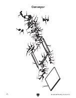


Model g0716 (Mfg. since 2/11)
-45-
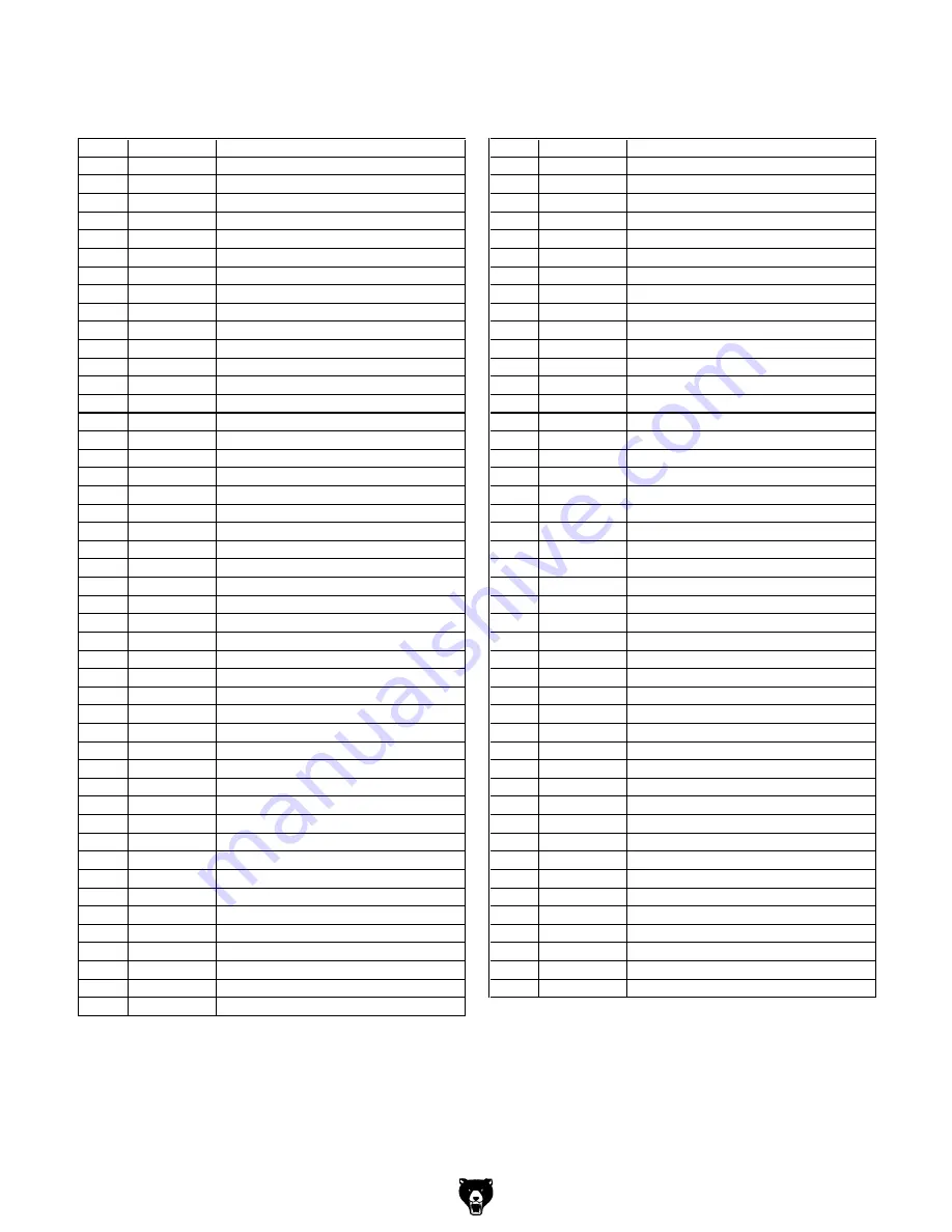
Main parts List
REF
PART #
DESCRIPTION
REF
PART #
DESCRIPTION
201
P0716201
CLUTCH DAMPER
250
PW06M
FLAT WASHER 12MM
202
PB26M
HEX BOLT M8-1.25 X 30
251
P0716251
ELEVATION ROTATION LABEL
203
P0716203
DUST HOOD
252
P0716252
HANDWHEEL ASSEMBLY
204
P0716204
DUST CONNECTOR 90 DEG 4"
253
P0716253
ELEVATION LEADSCREW
205
PLN04M
LOCK NUT M8-1.25
254
PK08M
KEY 5 X 5 X 16
206
P0716206
LOCKING PLATE
255
PB148M
HEX BOLT M5-.8 X 16
207
P0716207
DUST HOOD HANDLE
256
P0716256
SHAFT END CAP
208
PCAP31M
CAP SCREW M8-1.25 X 25
257
P0716257
STEEL BALL
209
PFH31M
FLAT HD SCR M4-.7 X 8
258
P0716258
BEARING RACE
210
P0716210
LEFT SANDPAPER CLAMP
259
P0716259
FRAME CASTING
211
PLW02M
LOCK WASHER 4MM
260
P0716260
LEADSCREW FLAT WASHER 16MM
212
PN04M
HEX NUT M4-.7
261
P0716261
THIN NUT M16-1.5
213V2 P0716213V2 SANDING DRUM V2.08.10
262
PS31M
PHLP HD SCR M6-1 X 35
214
P0716214
SANDPAPER 3"W X 63" 80GRIT
263
PB126M
HEX BOLT M8-1.25 X 40
215
P0716215
TORSION SPRING
264
PRP109M
ROLL PIN 6 X 26
216
PR19M
EXT RETAINING RING 28MM
265
P0716265
ELEVATION SCALE
217
P0716217
RIGHT SANDPAPER CLAMP
266
P0716266
OUTFEED ROLLER SUPPORT
218
P0716218
INTERNAL DRUM GUARD
267
P0716267
INFEED ROLLER SUPPORT
219
PFH26M
FLAT HD SCR M6-1 X 30
268
PLW04M
LOCK WASHER 8MM
220
P0716220
DUST HOOD HINGE
269
PB07M
HEX BOLT M8-1.25 X 25
221
PCB34M
CARRIAGE BOLT M8-1.25 X 25
270
P0716270
CONVEYOR SUPPORT
222
P0716222
OUTSIDE BEARING RETAINER
271
P0716271
THREADED STUD M8-1.25 X 80
223
P6205-2RS
BALL BEARING 6205-2RS
272
P0716272
DRUM HOUSING SUPPORT
224
P0716224
INTERNAL BEARING RETAINER
273
PWF08M
FENDER WASHER 8MM
225
P0716225
DRUM HOUSING
274
P0716274
KNOB M8-1.25
226
PW01M
FLAT WASHER 8MM
275
PB01M
HEX BOLT M10-1.5 X 30
227
PN03M
HEX NUT M8-1.25
276
PLW06M
LOCK WASHER 10MM
228
PN01M
HEX NUT M6-1
277
PW04M
FLAT WASHER 10MM
229
P0716229
POINTER
278
P0716278
MOTOR MOUNT
230
PCAP27M
CAP SCREW M6-1 X 14
279
P0716279
GIB
232
PW03M
FLAT WASHER 6MM
280
PCAP13M
CAP SCREW M8-1.25 X 30
233
P0716233
AUXILIARY GUARD
281
P0716281
MOTOR 1-1/2HP 110V 60HZ
234
PS40M
PHLP HD SCR M5-.8 X 16
281-1
P0716281-1
MOTOR FAN COVER
235
P0716235
DRUM CLUTCH
281-2
P0716281-2
MOTOR FAN
236
PSS03M
SET SCREW M6-1 X 8
281-3
P0716281-3
MOTOR JUNCTION BOX
237
PCAP39M
CAP SCREW M4-.7 X 20
281-4
P0716281-4
S CAPACITOR 80M 300V 2 X 3-5/8
238
PW05M
FLAT WASHER 4MM
281-5
P0716281-5
MOTOR CORD 14G 3C 18"
239
PW02M
FLAT WASHER 5MM
281-6
P0716281-6
CIRCUIT BREAKER CRU 12A
240
PLW01M
LOCK WASHER 5MM
282
PCAP45M
CAP SCREW M8-1.25 X 45
241
PS51M
PHLP HD SCR M4-.7 X 30
283
PAW06M
HEX WRENCH 6MM
242
P0716242
COMPRESSION SPRING
284
PAW05M
HEX WRENCH 5MM
243
P0716243
PRESSURE ROLLER BRACKET
285
PWR1113
COMBO WRENCH 11/13
244
P0716244
RIGHT BRACKET SUPPORT
286
PW01M
FLAT WASHER 8MM
245
P0716245
LEFT BRACKET SUPPORT
287
P0716287
SPACER 8MM
246
PLN01M
LOCK NUT M4-.7
288
PN06M
HEX NUT M5-.8
247
P0716247
PRESSURE ROLLER BUSHING
289
PB14M
HEX BOLT M10-1.5 X 35
248
P0716248
PRESSURE ROLLER
290
P0716290
HOLDING PIN
249
PN26M
ACORN NUT M12-1.75


