Grizzly G0702 Owner'S Manual Download Page 21

Model g0702 (Mfg. since 8/09)

-19-

review the troubleshooting and procedures in this section to fix or adjust your machine if a problem devel-
ops. if you need replacement parts or you are unsure of your repair skills, then feel free to call our technical 
Support at (570) 546-9663. 

SECtION 7: SERvICE

troubleshooting

Motor & Electrical

Symptom

possible Cause

possible Solution

Machine does not 
start.

1. Switch disabling key removed.

1. reinstall switch disabling key.

2. Break or short in wiring, loose connections,

plug or receptacle is corroded or miswired.

2. trace/replace broken or corroded wires, fix loose

connections, correct wiring.

3. power supply switched off/has incorrect

voltage.

3. Switch power supply on/verify voltage.

4. Blown fuse/tripped circuit breaker at main

panel.

4. Correct the cause of overload, then reset/replace

fuse or breaker.

5. Motor connection wired incorrectly.

5. Wire motor correctly (refer to inside junction box

cover or manual).

6. Motor on/oFF switch at fault.

6. replace switch.

7. Start capacitor has blown.

7. test/replace if at fault.

8. Centrifugal switch at fault.

8. adjust/replace centrifugal switch.

9. Motor at fault.

9. test for shorted windings or bad bearings; repair or

replace.

Machine has 
excessive vibration 
or noise.

1. Workpiece loose or incorrectly secured.

1. use correct holding fixture and re-clamp workpiece.

2. Motor fan rubbing on fan cover.

2. Fix/replace fan cover; replace loose or damaged fan.

3. Motor mounting loose.

3. tighten mounting bolts/nuts; use thread locking fluid.

4. lock lever is loose.

4. tighten the lock lever.

5. Machine incorrectly mounted to bench.

5. level/shim base; tighten/adjust mounting hardware

or feet.

6. Centrifugal switch out of adjustment; at fault. 6. adjust/replace centrifugal switch.
7. Motor bearings worn or damaged.

7. replace motor bearings or replace motor.

Machine stalls 
or slows when 
operating.

1. too much pressure when feeding workpiece 1. reduce pressure when feeding workpiece.
2. Workpiece is warped.

2. Straighten workpiece or use a different one.

3. Workpiece is incorrect for machine.

3. only sand wood and ensure moisture is below 20%.

4. Motor connection wired incorrectly.

4. review wiring diagram on motor cover; correct wire

connections.

5. Motor overheated.

5. let cool, clean motor, and reduce workload.

6. Centrifugal switch at fault.

6. adjust/replace centrifugal switch if available.

7. Motor at fault.

7. test, repair, or replace motor.

Summary of Contents for G0702

Page 1: ...nce 12 11 Copyright SEPTEMBER 2009 By Grizzly Industrial Inc REvised November 2011 KN Warning No portion of this manual may be reproduced in any shape Or form without the written approval of Grizzly I...

Page 2: ...g grinding tool integrity and the usage of personal protective equipment The manufacturer will not be held liable for injury or property damage from negligence improper training machine modifications...

Page 3: ...unting 12 Power Connection 12 Test Run 13 SECTION 4 OPERATIONS 14 Operation Overview 14 Attaching Sandpaper 15 X Y Miter Slots 15 Miter Sanding 16 Angle Sanding 16 SECTION 5 ACCESSORIES 17 SECTION 6 M...

Page 4: ...ed Please take a few minutes to give us feedback Grizzly Documentation Manager P O Box 2069 Bellingham WA 98227 2069 Email manuals grizzly com Contact Info We are proud to offer this manual with your...

Page 5: ...in Shipping Dimensions Type Cardboard Content Machine Weight 92 lbs Length x Width x Height 26 x 18 x 17 in Electrical Power Requirement 120V Single Phase 60 Hz Full Load Current Rating 9 5A Minimum...

Page 6: ...t Opening Not Visible G Adapter Base H Tilt Scale I Universal Lock Lever J Power Switch A B C D E F G H I J For Your Own Safety Read Instruction Manual Before Operating the Sander a Wear eye and ear p...

Page 7: ...rate under the influence of drugs or alcohol when tired or when distracted OWNER S MANUAL Read and understand this owner s manual BEFORE using machine Untrained users can be seriously hurt EYE PROTECT...

Page 8: ...not force machine It will do the job safer and better at the rate for which it was designed GUARDS COVERS Guards and covers can protect you from accidental contact with moving parts or flying debris M...

Page 9: ...se a workpiece holding fixture Sanding abrasives can quickly remove large amounts of skin AVOID WORKPIECE GRAB Support the workpiece on the work table against the rotation direction of the sanding dis...

Page 10: ...sult especially if connected to an undersized circuit To reduce the risk of these hazards avoid over loading the machine during operation and make sure it is connected to a power supply circuit that m...

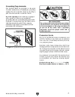
Page 11: ...nding Requirements This machine MUST be grounded In the event of certain malfunctions or breakdowns grounding reduces the risk of electric shock by providing a path of least resistance for electric cu...

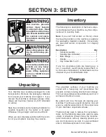
Page 12: ...e store Inventory The following is a description of the main compo nents shipped with your machine Lay the compo nents out to inventory them Note If you can t find an item on this list check the mount...

Page 13: ...isitors may be seriously injured if unsuper vised around this machine Lock entrances to the shop or disable start switch or power connection to prevent unsupervised use Site Considerations Figure 3 Mi...

Page 14: ...st mounting option is the Through Mount option Figure 4 where the holes are drilled all the way through the workbench and hex bolts washers and hex nuts are used to secure the machine Machine Base Wor...

Page 15: ...19 If you still cannot remedy a problem contact our Tech Support at 570 546 9663 for assistance To test run the machine 1 Rotate the disc by hand and make sure it turns freely 2 Make sure you have re...

Page 16: ...peration Overview This overview gives you the basic process that happens during an operation with this machine Familiarize yourself with this process to better understand the Operations section To com...

Page 17: ...the adhesive onto the surface Figure 9 Sandpaper being slipped between the disc and table The Model G0702 uses dual axis miter slot design for increased versatility of workpiece control or special ji...

Page 18: ...The disc table can be positioned from 15 to 45 relative to the plane of the sanding disc Sanding in an open angle zone rather than in a closed angle zone is typically safest Figure 12 Understanding th...

Page 19: ...00 G4256 12 PSA 120 G1222 12 PSA 150 G4257 12 PSA 180 G4258 12 PSA 220 G0572 Bench Top Dual Fan Dust Filter This Hanging Air Filter has a convenient remote control and features a three speed motor aut...

Page 20: ...ing dust with a dry cloth If any resin has built up use a resin dissolving cleaner to remove it Treat all unpainted cast iron and steel with a non staining lubricant after cleaning Cleaning Protect th...

Page 21: ...place centrifugal switch 9 Motor at fault 9 Test for shorted windings or bad bearings repair or replace Machine has excessive vibration or noise 1 Workpiece loose or incorrectly secured 1 Use correct...

Page 22: ...rse grit sandpaper or strip coating off before sanding 5 Sanding soft workpiece 5 Use different stock Or accept the characteristics of the stock and plan on cleaning replacing discs frequently Glossy...

Page 23: ...Disc Parallelism Figure 18 Squaring miter gauge to disc The edge of the table must be parallel with the face of the sanding disc and there should be a gap between the two This gap should be large enou...

Page 24: ...rewdriver loosen the degree scale pointer index the pointer on 0 and retighten the screw 5 Recheck the scale accuracy with the square When the table tilt is set to 90 the table should be positioned pe...

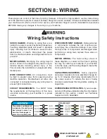
Page 25: ...napproved after market parts WIRE CONNECTIONS All connections must be tight to prevent wires from loosening during machine operation Double check all wires dis connected or connected during any wiring...

Page 26: ...iewed from behind Ground Neutral Hot Ground 120 VAC 5 15 PLUG START CAPACITOR 300MFD 125VAC MOTOR 120VAC REGULATOR TYPE CS 021 MOTOR ELECTRICAL BOX COVER The motor wiring shown here is current at the...

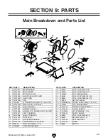
Page 27: ...3 3 P0702003 3 FAN 21 PN03M HEX NUT M8 1 25 3 4 PC300B S CAPACITOR 300M 125V 1 3 4 X 3 3 8 23 PWRCRD110L POWER CORD 16AWG X 3C X 73 L 3 5 P0702003 5 REGULATOR TYPE CS 021 29 PW03M FLAT WASHER 6MM 4 P0...

Page 28: ...MACHINE ID LABEL CSA V2 11 11 102 P0702102 GUARD WARNING LABEL 105 PLABEL 14B ELECTRICITY LABEL 101 100 102 103 104V2 105 Safety labels help reduce the risk of serious injury caused by machine hazard...

Page 29: ...metalworker ____ 0 2 Years ____ 2 8 Years ____ 8 20 Years ____20 Years 6 How many of your machines or tools are Grizzly ____ 0 2 ____ 3 5 ____ 6 9 ____10 7 Do you think your machine represents a good...

Page 30: ...LINE FOLD ALONG DOTTED LINE GRIZZLY INDUSTRIAL INC P O BOX 2069 BELLINGHAM WA 98227 2069 Place Stamp Here Name_______________________________ Street_______________________________ City______________S...

Page 31: ...he State of Washington County of Whatcom We shall in no event be liable for death injuries to persons or property or for incidental contingent special or consequential damages arising from the use of...

Page 32: ...Buy Direct and Save with Grizzly Trusted Proven and a Great Value Since 1983 ORDER 24 HOURS A DAY 1 800 523 4777 Visit Our Website Today For Current Specials...

Reviews: