background image

COPYRIGHT © JULY, 2009 BY GRIZZLY INDUSTRIAL, INC., REVISED SEPTEMBER, 2019 (RS)

WARNING: NO PORTION OF THIS MANUAL MAY BE REPRODUCED IN ANY SHAPE

 OR FORM WITHOUT THE WRITTEN APPROVAL OF GRIZZLY INDUSTRIAL, INC.

#TRCRBLTSJB11908  PRINTED IN TAIWAN

V2.09.19

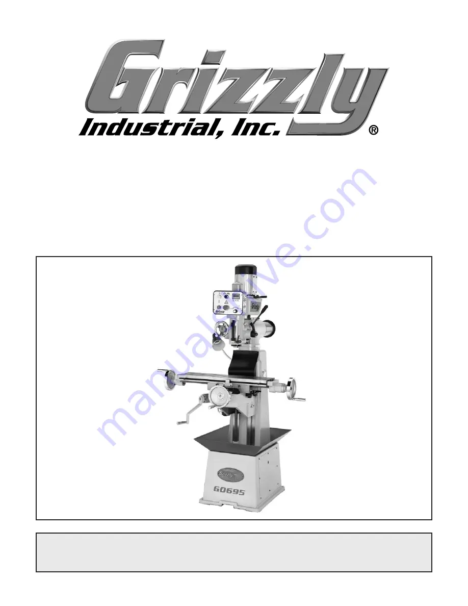
MODEL G0695

VS MILLING MACHINE w/RAM HEAD

OWNER'S MANUAL

(For models manufactured since 01/17)

Summary of Contents for G0695

Page 1: ...RS WARNING NO PORTION OF THIS MANUAL MAY BE REPRODUCED IN ANY SHAPE OR FORM WITHOUT THE WRITTEN APPROVAL OF GRIZZLY INDUSTRIAL INC TRCRBLTSJB11908 PRINTED IN TAIWAN V2 09 19 MODEL G0695 VS MILLING MA...

Page 2: ...g grinding tool integrity and the usage of personal protective equipment The manufacturer will not be held liable for injury or property damage from negligence improper training machine modifications...

Page 3: ...tion 19 Assembly 19 Power Connection 20 Test Run 20 Spindle Break In 21 SECTION 4 OPERATIONS 22 Operation Overview 22 Table Movement 23 Headstock Tilting 24 Headstock Turret Rotation 26 Headstock Ram...

Page 4: ...nufacture Date Serial Number Contact Info We stand behind our machines If you have ques tions or need help contact us with the information below Before contacting make sure you get the serial number a...

Page 5: ...ed Selector Lamp X Axis Handwheel Z Axis Crank Handle One Shot Oiler Base Splash Pan Belt Access Plate Coarse Downfeed Handle Y Axis Feed Limit Stops Longitudinal Limit Stops Identification To reduce...

Page 6: ...ntrols Table Locks G K N H I G M H Refer to Figure 1 and the following descriptions to become familiar with the basic controls and com ponents of this machine Understanding these items and how they wo...

Page 7: ...ill Lock Locks the quill in place but does not affect spindle rotation T Downfeed Stop Lock Stops downfeed travel when the quill dog reaches this point Set the stop at any position along the downfeed...

Page 8: ...d for Full Range of Movement Width x Depth 68 x 49 in Shipping Dimensions Type Wood Crate Content Machine Weight 1006 lbs Length x Width x Height 45 x 44 x 86 in Must Ship Upright Yes Electrical Power...

Page 9: ...Thickness 2 in Number of T Slots 3 T Slot Size 1 2 in T Slots Centers 2 3 16 in Spindle Info Spindle Taper R 8 Number of Vertical Spindle Speeds Variable Range of Vertical Spindle Speeds 220 2250 RPM...

Page 10: ...d proof DANGEROUS ENVIRONMENTS Do not use machinery in areas that are wet cluttered or have poor lighting Operating machinery in these areas greatly increases the risk of accidents and injury MENTAL A...

Page 11: ...moving parts or flying debris Make sure they are properly installed undamaged and working correctly BEFORE operating machine FORCING MACHINERY Do not force machine It will do the job safer and better...

Page 12: ...or have fingers amputated from contact with rotating cutters You can be blinded or struck by broken cutting tools metal chips workpieces or adjustment tools thrown from the rotating spindle with grea...

Page 13: ...e Gib A piece of metal placed along a sliding mem ber to take up wear or to ensure a proper fit The following is a list of common definitions terms and phrases used throughout this manual as they rela...

Page 14: ...k of these hazards avoid over loading the machine during operation and make sure it is connected to a power supply circuit that meets the specified circuit requirements Circuit Requirements for 220V T...

Page 15: ...hese grounding requirements or if you are in doubt about whether the tool is properly grounded If you ever notice that a cord or plug is damaged or worn discon nect it from power and immediately repla...

Page 16: ...y them If any non proprietary parts are missing e g a nut or a washer we will gladly replace them or for the sake of expediency replacements can be obtained at your local hardware store Inventory Figu...

Page 17: ...the following Disposable rags Cleaner degreaser WD 40 works well Safety glasses disposable gloves Plastic paint scraper optional Basic steps for removing rust preventative 1 Put on safety glasses 2 C...

Page 18: ...onment The physical environment where the machine is operated is important for safe operation and lon gevity of machine components For best results operate this machine in a dry environment that is fr...

Page 19: ...r to avoid cracking or warping the cast iron Move Headstock and Table Completely Inward Leveling machinery helps precision components such as dovetail ways remain straight and flat during the lifespan...

Page 20: ...nytime local codes apply you MUST follow the anchoring methodology specified by the code Machine Base Concrete Lag Screw Lag Shield Anchor Flat Washer Drilled Hole Figure 12 Popular method for anchori...

Page 21: ...he crank handle from its shipping position then re install the retain ing ring see Figure 15 Figure 14 Handle attached to handwheel Handle Figure 15 Vertical crank handle properly installed Retaining...

Page 22: ...nsure it is properly connected to power and safety components are functioning correctly If you find an unusual problem during the test run immediately stop the machine disconnect it from power and fix...

Page 23: ...machine is operating correctly by pushing the ON button When operating correctly the machine runs smoothly with little or no vibration or rubbing noises Investigate and correct strange or unusu al noi...

Page 24: ...ch 6 Unlocks the X and Y axis table locks then secures the Z axis lock SECTION 4 OPERATIONS Operation Overview The purpose of this overview is to provide the nov ice machine operator with a basic unde...

Page 25: ...graduated dials are marked in increments of 0 001 with a full revolution of the handwheel moving the table 0 125 Figure18 X axis table locks X Axis Table Locks Figure 19 Y axis and Z axis locks Y Axis...

Page 26: ...revent head stock binding and insufficient support do not tilt the headstock to a full 90 Binding occurs when one of the hex bolts on the side of the headstock Figures 23 24 binds in the T slot Figure...

Page 27: ...ck lock nuts during the following steps The head stock is very heavy and may be difficult to control once it is tilted past 45 R or 45 L If you do not pay attention it can flip over causing serious pe...

Page 28: ...head during operations could cause the cutter to bind with the workpiece causing damage to the cutter and workpiece and possible personal injury 2 Loosen the three locking hex nuts on the tur ret see...

Page 29: ...o move the ram inward or outward 1 DISCONNECT MILL FROM POWER 3 Push or pull the headstock in the direction of desired ram movement 4 Loosen the two raised cap screws to allow the clamp to close then...

Page 30: ...iled information Figure 29 Cutting speed table for HSS cutting tools 3 Use the following formula to calculate the required spindle speed RPM for your opera tion Cutting Speed FPM x 12 Recommended Tool...

Page 31: ...ad it If the tool does not release from the spindle taper when the drawbar is unthreaded turn the drawbar back into the tool five to ten threads then tap the top of the drawbar with a dead blow hammer...

Page 32: ...or slip Buy in bulk and save with 1 or 5 gallon quantities Figure 35 ISO 68 and ISO 32 machine oil T23962 T23963 T26685 Figure 33 Recommended products for machine lubrication SB1365 South Bend Way Oil...

Page 33: ...h Bend 8 Pc R8 Collet Set SB1349 South Bend 16 Pc R8 Collet Set Get true South Bend quality and precision with one of these Quick Change Collet Sets Each set includes hardened and precision ground spr...

Page 34: ...er bearings are internally lubricated and sealed at the factory Simply leave them alone unless they need to be replaced Before adding lubricant clean debris and grime from the devices to avoid contami...

Page 35: ...ull then pull the handle see Figure 41 and release it to send lubricant through the lines Figure 41 One shot oiler Oil Line One Shot Pump Handle Fill Cap Quill Gearing Lubricant Frequency Qty ISO 68 L...

Page 36: ...emove the belt cover and inspect the belt for cracking slipping or fraying If the belt shows signs of excessive wear replace it as outlined in Belt Replacement on Page 38 However with normal use the b...

Page 37: ...e sharp and correct cutting tool for the operation 4 Correct motor wiring connections Page 41 5 Test for good contacts correct the wiring 6 Replace loose pulley shaft 7 Test by rotating shaft rotation...

Page 38: ...ng not secure or is damaged 4 Spindle speed feed rate too fast 5 Gibs are too loose 1 Tighten all locks on mill that are not associated with movement for the operation 2 Check that clamping is tight a...

Page 39: ...d between the stationary and moving surfaces The saddle and knee have a gib on both sides There are two adjustment screws one on each end of each gib that move the tapered gib back and forth increasin...

Page 40: ...to tighten or loosen the cap screws on the leadscrew nuts shown in Figures 50 51 then test the amount of backlash by slowly rocking the handwheels back and forth Figure 51 Cross leadscrew nut Gap Gap...

Page 41: ...V belt tension lever Lock Bolt Belt Tension Lever 8 Re install the belt cover the belt access plate and return the headstock to the vertical position 7 Push firmly and hold the belt tension lever towa...

Page 42: ...t at the time of printing but may not match your machine If you find this to be the case use the wiring diagram inside the motor junction box CAPACITORS INVERTERS Some capacitors and power inverters s...

Page 43: ...X4 X3 X2 X1 X6 X5 COM REV COM FWD R S T U V W Ground Ground 1NC 2 4 3NO 3NO 4 1NC 2 V3 V2 V1 V3 V2 V1 1 1 2 2 6 6 6 2 2 3 3 0 0 12 12 13 13 Direction Switch ON Button Stop Button Power Lamp 30V Speed...

Page 44: ...42 Model G0695 Mfd Since 01 17 READ ELECTRICAL SAFETY ON PAGE 40 Electrical Components Figure 55 Control panel wiring Figure 56 Motor junction box Figure 57 Wiring component location...

Page 45: ...436 421 436 437 438 420 435 434 420 433 416 415 432 431 421 418 401 426 425 415 416 417 418 419 420 421 422 421 418 423 424 425 426 427 428 429 459 463 464 460 455 458 460 461 462 457 430 404 466 467...

Page 46: ...PANNER NUT 20MM 448 P0695448 HEX BOLT M6 1 X 30 416 P0695416 SPANNER LOCK WASHER 20MM 449 P0695449 HEX BOLT 1 2 13 X 2 417 P0695417 BEVEL GEAR 450 P0695450 LOCK WASHER 1 2 418 P0695418 BALL BEARING 60...

Page 47: ...r Parts Store Head 101 102 160 104 105 106 107 108 109 110 111 112 113 114 115 116 117 118 110 162 121 158 157 150 151 152 153 154 155 156 122 123 124 125 127 128 129 127 130 131 149 148 146 147 146 1...

Page 48: ...4 TORSION SPRING 148 P0695148 KEY 5 X 5 X 20 115 P0695115 FLANGE COVER 149 P0695149 WORM SHAFT 116 P0695116 EXT RETAINING RING 19MM 150 P0695150 COUPLING WORM GEAR 117 P0695117 DOWNFEED LEVER 151 P069...

Page 49: ...visit our Parts Store Motor Ram 201 241 243 242 244 240 239 238 237 236 235 245 202 203 246 234 233 204 205 206 232 231 230 229 209 225 226 228 227 224 224 207 208 209 223 210 209 222 211 212 213 214...

Page 50: ...232 SET SCREW M6 1 X 8 208 P0695208 V BELT COVER RIGHT 233 P0695233 FLAT WASHER 8MM 209 P0695209 PHLP HD SCR M5 8 X 12 234 P0695234 CAP SCREW M8 1 25 X 25 210 P0695210 RAM END COVER 235 P0695235 CONTR...

Page 51: ...DLE 3L 3 8 16 X 1 307 P0695307 CAP SCREW M6 1 X 25 329 P0695329 LONGITUDINAL LOCK HANDLE 308 P0695308 SPACER 330 P0695330 CAP SCREW M6 1 X 16 309 P0695309 EXT RETAINING RING 20MM 331 P0695331 HEX NUT...

Page 52: ...g gloves or jewelry tie back long hair and roll up long sleeves 5 Always remove wrenches chuck keys or other adjustment tools before starting 6 Always clamp workpiece to table before cutting never att...

Page 53: ...metalworker ____ 0 2 Years ____ 2 8 Years ____ 8 20 Years ____20 Years 6 How many of your machines or tools are Grizzly ____ 0 2 ____ 3 5 ____ 6 9 ____10 7 Do you think your machine represents a good...

Page 54: ...LINE FOLD ALONG DOTTED LINE GRIZZLY INDUSTRIAL INC P O BOX 2069 BELLINGHAM WA 98227 2069 Place Stamp Here Name_______________________________ Street_______________________________ City______________S...

Page 55: ...shall be tried in the State of Washington County of Whatcom We shall in no event be liable for death injuries to persons or property or for incidental contingent special or consequential damages arisi...

Page 56: ......

Reviews: