


-48-
G0609 12" Parallelogram Jointer
REF
PART #
DESCRIPTION
REF
PART #
DESCRIPTION
1
P0609001
CUTTERHEAD GUARD
46
PLW06M
LOCK WASHER 10MM
4
PFH23M
FLAT HD SCR M8-1.25 X 16
47
PB32M
HEX BOLT M10-1.5 X 25
5
P0609005
SPECIAL FLAT WASHER
48
P0609048
BUSHING
6
PSS04M
SET SCREW M6-1 X 12
49
P0609049
WORM GEAR
7
P0609007
ADAPTER
50
PK12M
KEY 5 X 5 X 30
8
P0609008
TORSION SPRING
51
P0609051
GEAR
9
P0609009
SHAFT COLLAR
52
P0609052
WORM
10
PSS04M
SET SCREW M6-1 X 12
53
PK37M
KEY 4 X 4 X 16
11
P0609011
SHAFT
54
P0609054
SLIDE STOP BLOCK
12
P0609012
SPECIAL CUTTERHEAD SCREW
55
P0609055
SLIDE STOP BLOCK
13
PLW06M
LOCK WASHER 10MM
55-1
PSS16M
SET SCREW M8-1.25 X 10
14
PW04M
FLAT WASHER 10MM
56
P0609056
SPECIAL FLAT SCREW
15
PK111
KEY 8 X 8 X 60
57
P0609057
POINTER
16
P0609016
CUTTERHEAD PULLEY
58
PW02M
FLAT WASHER 5MM
17
PVA54
V-BELT A-54 4L540
59
PS09M
PHLP HD SCR M5-.8 X 10
18
PSB02M
CAP SCREW M6-1 X 20
60
PB73M
HEX BOLT M10-1.5 X 50
19
P0609019
BEARING COVER
61
P0609061
CLAMP BLOCK
20
P6206
BALL BEARING 6206ZZ
62
PLW06M
LOCK WASHER 10MM
21
P0609021
BEARING SUPPORT
63
PW04M
FLAT WASHER 10MM
22
PFH05M
FLAT HD SCR M5-.8 X 12
64
P0609064
CLAMPING BLOCK
23
P0609023
CUTTERHEAD
65
P0609065
CLAMP PLATE
24
P0609024
KNIFE
66
PHTEK4M
TAP SCREW M4 X 8
25
P0609025
KNIFE BAR (GIB)
67
P0609067
STOP BUTTON
26
P0609026
KNIFE LOCK SCREW (GIB SCREW)
68
P0609068
START BUTTON
27
P0609027
BEARING SUPPORT
69
P0609069
SWITCH BOX
28
P62042RZ
BALL BEARING 62042RZ
70
PFS16M
FLANGE SCREW M8-1.25 X 16
29
PW01M
FLAT WASHER 8MM
71
P0609071
SWITCH BOX BRACKET
30
P0609030
CUTTERHEAD SCREW
72
PB32M
HEX BOLT M10-1.5 X 25
31
PN02M
HEX NUT M10-1.5
73
PLW06M
LOCK WASHER 10MM
32
P0609032
BEARING COVER
74
PW04M
FLAT WASHER 10MM
33
PSB02M
CAP SCREW M6-1 X 20
75
P0609075
BUTTON PLATE
34
PB156
HEX BOLT M10-1.5 X 150
76
P0609076
BALL STRAIN RELIEF
35
PSS71M
SET SCREW M10-1.5 X 60
77
PAW10M
HEX WRENCH 10MM
36
P0609036
BASE
78
PAW08M
HEX WRENCH 8MM
37
PSS04M
SET SCREW M6-1 X 12
79
PAW03M
HEX WRENCH 3MM
38
PW04M
FLAT WASHER 10MM
80
PWR1719
WRENCH 17 X 19
39
P0609039
LOCK HANDLE
81
PWR1214
COMBO WRENCH 12/14MM
40
PSS03M
SET SCREW M6-1 X 8
82
PWR1012
COMBO WRENCH 10/12MM
41
P0609041
ECCENTRIC BUSHING
83
P0609083
T-HANDLE WRENCH 4MM
42
P0609042
SHAFT
84
P0609084
BUSHING
42-1
P0609042-1
LEFT TORSION SPRING
85
P6202
BALL BEARING 6202ZZ
42-2
P0609042-2
RIGHT TORSION SPRING
86
PB06M
HEX BOLT M8-1.25 X 12
43
P0609043
STOP BLOCK
87
PW03M
FLAT WASHER 6MM
44
PR21M
INT RETAINING RING 35MM
88
PB02M
HEX BOLT M6-1 X 12
45
P0609045
SHAFT
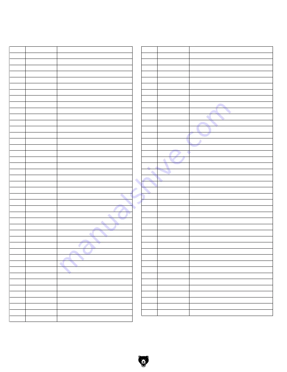
Base Parts List
Summary of Contents for G0609
Page 3: ......
Page 10: ...G0609 12 Parallelogram Jointer 7 SECTION 1 SAFETY...
Page 11: ...8 G0609 12 Parallelogram Jointer...
Page 16: ...G0609 12 Parallelogram Jointer 13 Hardware Recognition Chart...
Page 49: ...46 G0609 12 Parallelogram Jointer G0609 Wiring Diagram...
Page 50: ...G0609 12 Parallelogram Jointer 47 Base Assembly Parts Breakdown...
Page 54: ...G0609 12 Parallelogram Jointer 51 Stand Assembly Parts Breakdown...
Page 58: ......
Page 59: ......
Page 60: ......
Page 61: ......


