background image

H8151 230V Mini Welder

-13-

Review the troubleshooting and procedures in this section to fix or adjust your machine if a problem devel-
ops. If you need replacement parts or you are unsure of your repair skills, then feel free to call our Technical 
Support at (570) 546-9663. 

SECTION 6: SERVICE

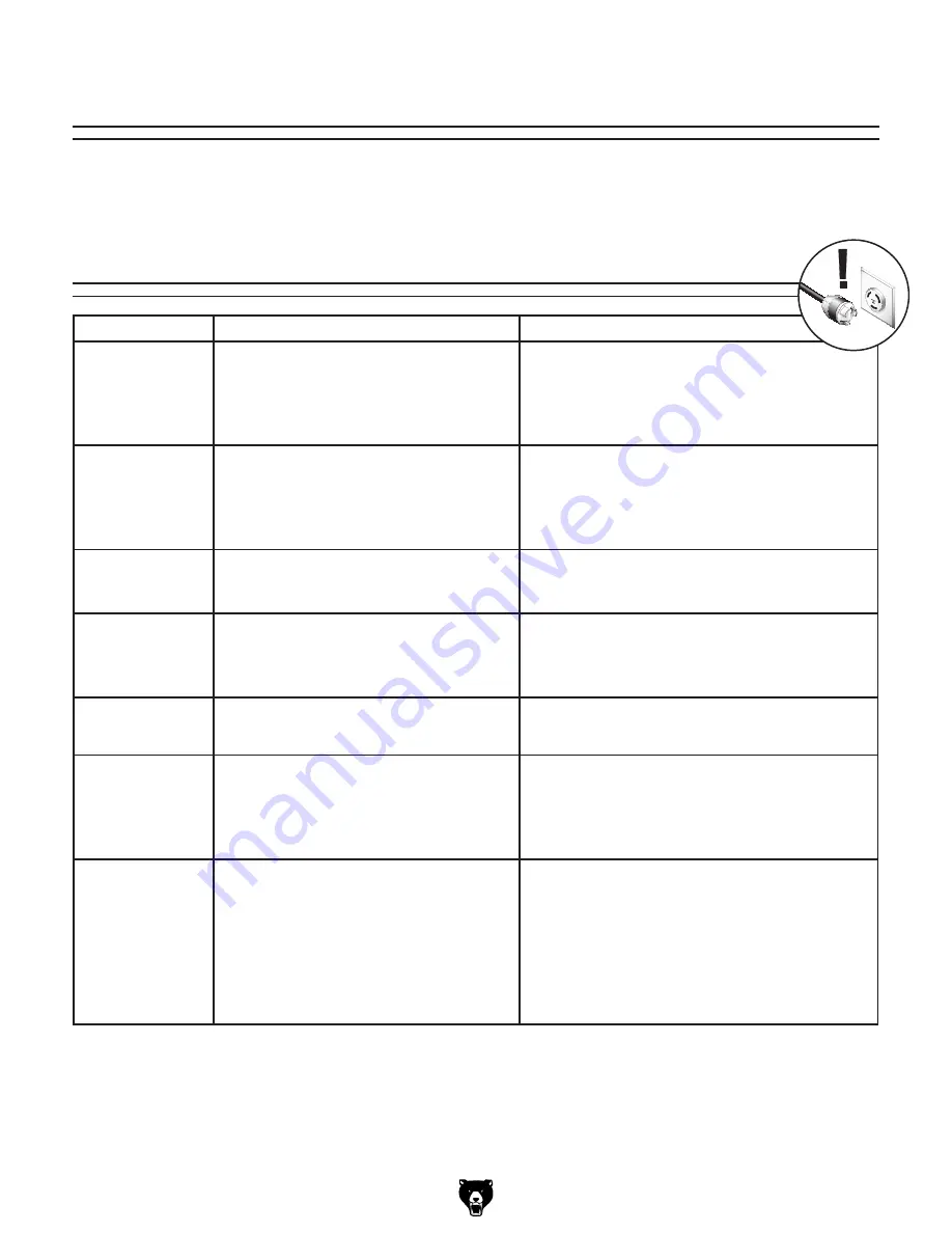
Troubleshooting

Symptom

Possible Cause

Possible Solution

Welder  does  not 
power  up  or  the 
breaker trips.

1.  Plug/receptacle  is  at  fault  or  wired  incor-

rectly.

2.  Wiring is open/has high resistance.

3.  ON/OFF switch is at fault.

1.  Test for good contacts; correct the wiring.

2.  Check  for  broken  wires  or  disconnected/corroded 

connections, and repair/replace as necessary. 

3.  Replace faulty ON/OFF switch.

Porosity; small cavi-
ties or holes caused 
from  gas  packets  in 
weld.

1.  Arc length is too long.
2.  Workpiece is dirty.

3.  Damp electrodes.
4.  Incorrect electrode used.

1.  Reduce length of arc.
2.  Remove all grease, oil, moisture, coatings, rust, and 

dirt from workpiece before welding.

3.  Use dry electrodes.
4.  Use correct type and size of electrode.

Excessive spatter.

1.  Amperage too high for electrode.
2.  Voltage too high; arc length too long.
3.  Incorrect electrode used.

1.  Select large electrode or decrease amperage.
2.  Reduce voltage or arc length.
3.  Use correct type and size of electrode.

Distortion  of  base 
metal.

1.  Excessive heat applied to base metal.

1.  Make  tack  welds  along  joint  before  starting  opera-

tion;  select  lower  amperage  for  electrode;  increase 
travel speed; weld in small segments and allow cool-
ing between welds.

Burn  through  or 
excessive  penetra-
tion of base metal.

1.  Excessive heat applied to base metal.

1.  Select  lower  amperage;  use  smaller  electrode; 

increase and/or maintain steady travel speed.

Lack of penetration. 1.  Improper joint preparation.

2.  Improper weld technique.

3.  Insufficient heat applied to weld.

1.  Material  too  thick;  joint  preparation  must  provide 

access to bottom of groove.

2.  Keep  arc  on  leading  edge  of  weld  puddle;  reduce 

travel speed.

3.  Increase amperage; select larger electrode.

Failure  of  weld  to 
fuse completely with 
base  metal  or  prior 
weld bead.

1.  Insufficient heat applied to weld.
2.  Improper welding technique.

3.  Workpiece dirty.

4.  Duty cycle exceeded.

1.  Increase amperage; select larger electrode.
2.  Widen  groove  to  access  bottom  during  welding; 

keep  arc  on  leading  edge  of  weld  puddle;  place 
stringer bead in proper location at joint during weld-
ing.

3.  Remove all grease, oil, moisture, coatings, rust, and 

dirt from workpiece before welding.

4.  Shut down welder and allow it to cool.

Troubleshooting

Summary of Contents for 230V

Page 1: ...NI WELDER OWNER S MANUAL COPYRIGHT MAY 2007 BY GRIZZLY INDUSTRIAL INC WARNING NO PORTION OF THIS MANUAL MAY BE REPRODUCED IN ANY SHAPE OR FORM WITHOUT THE WRITTEN APPROVAL OF GRIZZLY INDUSTRIAL INC TS9041 PRINTED IN CHINA ...

Page 2: ... ...

Page 3: ...tional Sources for Welding Codes and Standards 6 SECTION 2 CIRCUIT REQUIREMENTS 7 220V Operation 7 Grounding for Arc Welding Safety 8 SECTION 3 INVENTORY 9 SECTION 4 OPERATIONS 10 Operation Safety 10 Welder Duty Cycle 10 General Arc Welding Operations 11 SECTION 5 ACCESSORIES 12 SECTION 6 SERVICE 13 Troubleshooting 13 Replacement Parts And Labels 14 WARRANTY AND RETURNS 17 ...

Page 4: ...n the part of Grizzly For your convenience we always keep current Grizzly manuals available on our website at www grizzly com Any updates to your machine will be reflected in these manuals as soon as they are complete Visit our site often to check for the lat est updates to this manual Contact Info If you have any comments regarding this manual please write to us at the address below Grizzly Indus...

Page 5: ...tification A Electrode Holder and Cable B Negative Output Socket C Power Lamp D Temperature Warning Lamp E Carrying Strap F Variable Current Output Dial G Positive Output Socket H Work Clamp and Cable I Power Cord J ON OFF Switch K Cooling Fan and Cover L Welder Enclosure Ground Terminal Figure 1 Model H8151 front view C D F G B A H E Figure 2 Model H8151 rear view I L J K ...

Page 6: ...zone and the general area Use ANSI approved respirators for the type of welding operation Protect others from these fumes 3 WELDING IN A CONFINED SPACE CAN BE HAZARDOUS Always open all covers sustain forced ventilation remove toxic and hazardous materials and provide a power disconnect to the welder inside the work space Always work with someone who can give you help from outside the space Welding...

Page 7: ...ep lead cables orga nized and away from your body 8 AVOID EXPLOSION HAZARD Never weld on closed containers or containers with fumes inside Containers should be prepared per American Welding Society Publication F4 1 Section 7 8 ELECTRIC AND MAGNETIC FIELDS EMF Welding operations create EMF around the welding equipment and workpieces Workers who have pacemak ers must consult with their physician bef...

Page 8: ...t P 1 Canadian Standards Association Standards Sales 178 Rexdale Boulevard Rexdale Ontario Canada M9W 1R3 800 463 6727 Website www csa international org Code for Safety in Welding and Cutting CSA Standard W117 2 American National Standards Institute ANSI 11 West 42nd Street New York NY 10036 8002 212 642 4900 Website www ansi org Practice for Occupational and Educational Eye and Face Protection AN...

Page 9: ...ed to do so 220V Operation Grounding In the event of an electrical short grounding reduces the risk of electric shock The grounding wire in the power cord must be properly connected to the grounding prong on the plug likewise the outlet must be properly installed and grounded All electrical connections must be made in accor dance with local codes and ordinances Electrocution or fire could result i...

Page 10: ...orkpiece Ground The incoming power circuit to the welder and the welding circuit are two separate circuits that must have separate grounds The welding circuit consists of the internal components of the welder the welding cables the electrode holder the work clamp and the workpiece In the publication Safety in Welding Cutting and Allied Processes ANSI Publication Z49 1 11 3 2 1 it is specified that...

Page 11: ... the containers and all packing materials for possible inspection by the carrier or its agent Otherwise filing a freight claim can be difficult When you are completely satisfied with the condition of your shipment inventory the contents Figure 5 Model H8151 inventory C D E F G B H A A Polyurethane Carrying Case B Welder Carrying Strap C 230V Mini Welder D Work Clamp and Cable E Utility Brush and S...

Page 12: ...ver heating each welder has an established duty cycle The duty cycle is vari able depending upon the amperage output being used A duty cycle is the number of minutes out of 10 minutes that the welder can safely operate at the current amperage output without over heating For instance the Model H8151 has a duty cycle of 60 at 95A output This means that the welder can operate continuously for 6 out o...

Page 13: ...r stand by to assist if needed 4 Select the correct electrode type and size for your welding project 5 Choose the correct amperage output and be aware of the duty cycle for this amperage 6 Decide which type of weld is correct for your project and properly prepare the metal 7 Make sure the welding cables and grounds are secure Note Insert the welding cable connectors into the welder output sockets ...

Page 14: ...for welding applications Special depth filter pro vides high loading capacity for metal fumes with out increasing breathing resistance Heavy duty adjustable headstrap and soft closed cell foam face seal offers maximum comfort protection and fit 5 pack Figure 7 Model G7868 welding respirators Figure 8 Models H9748 H9746 H9745 leather welding protection H9748 Leather Jacket Medium 40 42 H9887 Leathe...

Page 15: ...arge electrode or decrease amperage 2 Reduce voltage or arc length 3 Use correct type and size of electrode Distortion of base metal 1 Excessive heat applied to base metal 1 Make tack welds along joint before starting opera tion select lower amperage for electrode increase travel speed weld in small segments and allow cool ing between welds Burn through or excessive penetra tion of base metal 1 Ex...

Page 16: ...ntact Grizzly at 800 523 4777 or www grizzly com to order new labels Replacement Parts And Labels REF PART DESCRIPTION REF PART DESCRIPTION 1 PH8151001 POLYURETHANE CARRYING CASE 7 PH8151004 WELDERS MASK HANDLE 2 PH8151002 CARRYING STRAP 8 PLABEL 14 ELECTRICITY LABEL 3 PH8151003 WORK CLAMP CABLE 9 PH8151009 SHOCK HAZARD LABEL 4 PH8151007 UTILITY BRUSH PICK 10 PH8151010 MACHINE ID LABEL 5 PH8151008...

Page 17: ... ...

Page 18: ... ...

Page 19: ...the State of Washington County of Whatcom We shall in no event be liable for death injuries to persons or property or for incidental contingent special or consequential damages arising from the use of our products To take advantage of this warranty contact us by mail or phone and give us all the details We will then issue you a Return Number which must be clearly posted on the outside as well as t...

Page 20: ... ...

Reviews: