28
English
3.
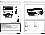
Let the signal cables pass through the cable glands
“M”
located onto the rear panel of the unit and connect the
DMX signal cables to the pin
“N”
.
The connection of the cable to the unit must be per-
formed respecting the label next to the terminal box,
while from the end of the DMX controller the connection
must respect the following table:
pin 1 = GND
pin 2 = data -
pin 3 = data +
For DMX devices with 5 poles connectors, pins 4 and 5
are not to be connected.
Size and connection scheme of the DMX cable are
shown in the following picture.
4.
Close the unit again.
Warning!
All data wires must be isolated one from another, from the shield and from the metal housing of the connectors.
Pin number 1 of the housing is not to be connected to the electric ground of the unit.
Insert a terminal plug with a 120 Ω resistor connected to pins Data- and Data+ in the last unit.
ø5 MIN
ø10 MAX
Pin 1: GND
Pin 2: DATA-
Pin 3: DATA+
DMX cable size
M
DMX IN
DMX OUT
N