


Baserunner Controller User Manual
Rev 1.0
unloaded motor current. The “Motor Stall Timeout” setting determines when this
injection current will stop once the motor comes to a stop.
Once the values for “Virtual Electronic Freewheeling” are set, the controller will
draw about 10-40 watts in order to overcome the motor’s drag. Regenerative
braking should recapture more energy than lost due to the injection current.
Users of mid-drive motors can also use this feature to keep the drive train always
engaged, eliminating windup delay and harsh clutch engagement when throttle is
applied and the motor comes up to speed.
6 Additional Details:
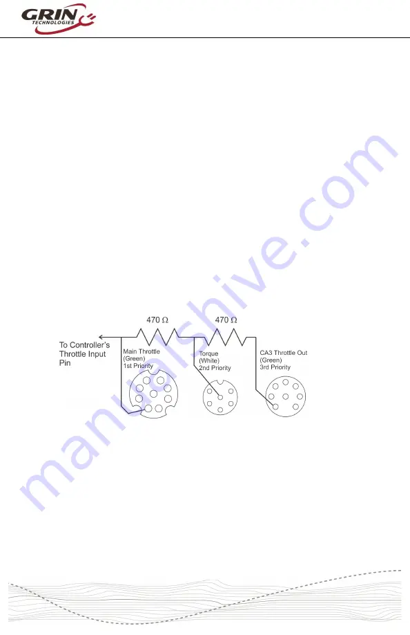
6.1 Throttle Priorities
The throttle input signal to the Baserunner controller is accessible through each
of the three signal connectors. These are wired with resistors in between them in
order to avoid conflict if two or more devices are attempting to drive this throttle
voltage. The resistor combination gives the throttle signal on the Mains cable the
highest priority, with the throttle signal on the PAS plug (typically used for a
torque signal) the second priority, and finally the throttle signal on the WP8 Cycle
Analyst plug has lowest priority.
Normally when a CA3 device is in use there is no hookup to the other two plugs
and the CA3's throttle output won't be overridden even though it has lowest
priority. If a torque sensor is plugged into the PAS plug, while a normal hall effect
throttle is hooked up to the Mains cable harness, then both the torque signal and
the throttle will operate in parallel to move the Baserunner's throttle input high.
6.2 Reverse Mode
The signal
PAS 2
used in the 6 pin PAS plug is electrically equivalent to the
FWD/REV
pin in the Main plug. This input is by default configured as a reverse
-20-