background image

17

 P0803466-00 v.2.0

OPERATING YOUR ZERO TURN MOWER

STARTING YOUR MOWER

•  With key inserted, turn master power ignition switch on by rotating key clockwise to the ON position.

•  Check for the appropriate speed mode by pressing drive speed control button to “low speed” position.

NOTE: It is always recommended to start out in low mode/slow speed.

•  Pull right and left drive control levers inward until stops are contacted.

•  Pull up on deck blades ON/OFF switch to start cutting blades for mowing.

NOTE: only engage blades when drive control levers are in the NEUTURAL position! NEVER engage 

blades when moving!!

•  Push drive control levers forward for forward motion and pull for reverse motion.

NOTE: Electric brake will engage after drive control levers are returned to neutral.
STOPPING YOUR MOWER

D A N G E R

Never make sudden stops or reverse direction, especially when maneuvering on a slope. The steering is 

designed for sensitive response. Rapid movement of the steering control levers in either direction could 

result in a reaction of the machine that can cause serious injury.

•  Return drive control levers to the Neutral/Park brake position.

•  Push down on deck blades ON/OFF to turn off the blades.

•  Push drive control levers outward into park brake position.

•  Rotate key in Master Power Ignition Switch counterclockwise to the OFF position.

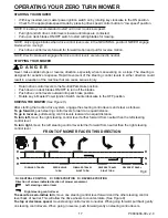
DRIVING THE MOWER


(See Figure 8.)

After starting the traction drive system, engage the steering control levers and steer as follows:

To go forward,

 push steering control levers forward an equal distance.

To go in reverse,

 pull steering control levers rearward an equal distance.

To turn left,

 move the right steering control lever farther forward from neutral than the left steering 

control lever.

To turn right,

 move the left steering control lever farther forward from neutral than the right steering

control lever.

FRONT OF MOWER FACES THIS DIRECTION 

N

N

FORWARD TRAVEL

ZERO-RADIUS

TURN

FORWARD TRAVEL 

RIGHT TURN

REVERSE TRAVEL 

RIGHT TURN

REVERSE TRAVEL

N = NEUTRAL POSITION

Direction of arrows indicate direction of mower movement

Left steering control lever

Right steering control lever

D

D

R

R

D = DRIVE POSITION R = REVERSE POSITION

To execute a zero-radius turn,

 move one steering control lever forward and the other steering control 

lever back of neutral. This will allow the drive wheels to counter-rotate. (See Figure 8)

To stop or decrease speed,

 move steering control levers to neutral. When going forward, pull back gently 

on steering control levers. When going in reverse, push forward gently on steering control levers.

Fig.8

Summary of Contents for 7404702

Page 1: ...Zero Turn Mower 7404702 Model No RZ48 Read all safety rules and instructions carefully before operating this machine Owner s Manual TOLL FREE HELPLINE 1 855 470 4267 www GreenworksCommercial com ...

Page 2: ...h operator seated 13 Right control panel with operator seated 13 Steering control levers 14 Steering alignment screw 14 Safety start interlock system 14 Anti scalp wheels 15 Deck height adjustment pedal 15 Neutral bypass knobs 16 Operation 17 Starting your mower 17 Stopping your mower 17 Driving the mower 17 Steering control lever adjustment 18 Seat adjustment 19 Deck cutting height adjustment 19 ...

Page 3: ...mower 32 No season preparation 33 Battery maintenance 34 Service 34 Environmentally safe battery disposal 36 Troubleshooting 37 Troubleshooting 37 Deck System Resistance Test Procedure 40 Limited warranty 41 PRODUCT SPECIFICATIONS CONTENTS Model No RZ48 Battery type 82V lithium ion Gross vehicle weight 704 lbs 320 kg Length overall 69 Width overall with discharge 53 Height overall 42 Deck width 48...

Page 4: ...facing forward unless otherwise stated Photographs and illustrations used were current at the time of printing but subsequent production changes may cause your machine to vary slightly in detail Greenworks reserves the right to redesign and change the machine as deemed necessary without notification If a change has been made to your machine which is not reflected in this owner s manual or the part...

Page 5: ...rstand and follow all instructions in this manual Become familiar with all controls and their proper operation Know how to stop the mower and how to disengage the power in an emergency Keep this manual in a safe place for reference and consult it regularly OPERATOR Only allow responsible capable adults who are familiar with the instructions to operate this machine Safe operation requires your full...

Page 6: ... grass Toreduce the risk of electric shock do not expose to water or operate on wet ground MOWING For riding mower models always remain seated while operating machine Do not operate on inclines greater than 15 degrees Mow only in daylight or in good artificial light Never rush a mowing job Never attempt high speed maneuvering especially in crowded congested areas or on slopes Do not operate within...

Page 7: ...d indoors in a dryand locked place out of reach of children Maintain your mower Keep cutting edges sharp and clean to ensure the best performance and safeoperation Remove or disconnect battery before servicing cleaning or removing material from lawnmower Do not open or mutilate the battery Mutilated batteries can release corrosive electrolytes which cancause damage to the eyes or skin It may be to...

Page 8: ...bjects thatmay obscure your view of a child who may run into the path of the mower Before and while backing look behind and down for small children Never carry children on the mower with you even with the blade s shut off They may fall off and beseriously injured or interfere with safe machine operation Children who have been given rides in thepast may suddenly appear in the mowing area for anothe...

Page 9: ... the temperature is more than 0 C 32 F but less than 45 C 113 F To reduce the risk of serious personal injury do not store outside or in vehicles Under extreme usage or temperature conditions battery leakage may occur If this liquid comes in contact with your skin wash immediately with soap and water If liquid gets into your eyes flush them with clean water for at least 10 minutes then seek immedi...

Page 10: ...not expose to rain or use in damp locations Read The Operator s Manual To reduce the risk of injury user must read and understand operator s manual before using this product Eye Protection Always wear safety glasses with side shields that are marked to comply with ANSI Z87 1 Keep Hands and Feet Away Keep hands and feet away from blade and cutting area No Slope Do not operate on inclines greater th...

Page 11: ...or service we suggest you return the product to your nearest AUTHORIZED SERVICE CENTER for repair When servicing use only identical replacement parts W A R N I N G To avoid serious personal injury do not attempt to use this product until you have read this Owner s Manual thoroughly and understand it completely If you do not understand the warnings and instructions in this Owner s Manual do not use...

Page 12: ...YOUR MOWER a b d e f g h i j c See Figure 1 No Name 1 Steering control levers 2 Right control panel 3 Left control panel 4 Deck 5 Anti scalp wheels 6 Front wheel 7 Drive wheel 8 Discharge chute 9 Deck height button 10 Attachment port 11 LED light Fig 1 k ...

Page 13: ...nd ON With key inserted rotate it clockwise to the ON position conterclockwise to OFF position Drive speed control button Press the button to drive in high speed means thatthe maximum drive speed will be 7 mph Press the button again to drive in low speed means that the maximum drive speed will be 4 mph Drive in low speed for inexperienced operators or when trimming around objects buildings and oth...

Page 14: ...injury due to unintentional traction drive system starting Check mower safety start interlock system daily prior to operation This system is an important mower safety feature It should be repaired immediately if it malfunctions Call Greenworks immediately The machine incorporates a separate seat switch which will stop the drive system and deck motors when the operator is unseated for any reason wh...

Page 15: ...e 5 Anti scalp wheel kits are standard on Greenworks units These anti scalp wheels are designed to minimize scalping when mowing on rough uneven terrain After setting the cutting height adjust the anti scalp wheels so they extend below the deck but do not contact the ground They should always be at least 1 4 to 3 4 below the deck With the unit sitting on a flat level surface the wheel position can...

Page 16: ...ls are chalked Locate the Neutral Bypass Knobs behind the frame at the rear of the mower NEUTRAL BYPASS KNOB See Figure 7 Move the neutral bypass knobs to the left and then downwards to unlock the wheels Move the neutral bypass knobs back into position to lock the wheels W A R N I N G Never drive mower with the neutral bypass knob working Always install the neutral bypass knob to the original posi...

Page 17: ...ff the blades Push drive control levers outward into park brake position Rotate key in Master Power Ignition Switch counterclockwise to the OFF position DRIVING THE MOWER See Figure 8 After starting the traction drive system engage the steering control levers and steer as follows To go forward push steering control levers forward an equal distance To go in reverse pull steering control levers rear...

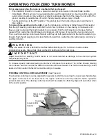
Page 18: ...trol levers forward until they are both past neutral and the machine starts to go forward Push the left steering control lever farther forward from neutral than the right steering control lever and finish the turn W A R N I N G Always be aware of what is behind the machine before backing up Do not mow in reverse unless absolutely necessary Always look down and behind before and while backing up I ...

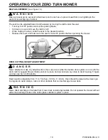
Page 19: ... is locked in position before operating the mower DECK CUTTING HEIGHT ADJUSTMENT D A N G E R Never attempt to make any adjustments to the mower deck while the traction drive system is on or with the deck clutch engaged Mower blades cannot be seen and are located very close to deck housing Fingers and toes can be cut off instantly Deck height is adjustable from 1 5 4 5 inches 3 81cm 11 43cm Deck sh...

Page 20: ...ction could cause sliding and loss of steering control Do not tow on slopes The weight of the towed equipment may cause loss of traction and control If the mower s tires lose traction when operating on slopes disengage the deck drive place the steering control levers in the park brake position turn the key to the OFF position and get help Never make sudden starts stops turns or reverse direction e...

Page 21: ... is located at the bottom of the slope This will reduce the risk of the machine suddenly rolling over causing serious injury or death Extreme caution should be used when there is a hazard located at the bottom of the slope Some examples are water e g lake river cliffs retaining walls roads highways buildings rocks These are just a few examples of situations where caution must be used when operatin...

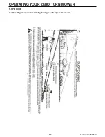
Page 22: ...22 P0803466 00 v 2 0 OPERATING YOUR ZERO TURN MOWER SLOPE GUIDE Use this diagram when determining the degree of slope to be mowed ...

Page 23: ... in accordance with applicable firecodes and ordinances to avoid fire hazards Proper ventilation is required to remove hydrogen gasfrom the area during battery charging Never allow flames sparks or smoking near batteries Keep batteries out of reach of children Always keep protective shields covers and guards in place and securely fastened If they becomedamaged repair or replace immediately Never m...

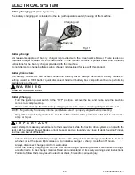
Page 24: ...omplete stop Remove the dust cap from the battery charging port on the mower and plug charger into the port NOTE Plug will only fit one way into the port Make sure it is properly aligned before inserting Plug other end of charger into 100 to 120 volt household GFCI protected outlet that is rated at 15 amps or higher I M P O R T A N T Never attempt to make any adjustments to the mower deck while th...

Page 25: ...nly be operated by distributor Open battery compartment and lift up battery cover to expose Lithium Modules Grasp RED BATTERY QUICK DISCONNECT HANDLE by wall of mower Pull INWARD on lever until disengaged from wall plug Unplug all red battery connectors by grasping each red plug and pull apart DO NOT PULL ON BATTERY CABLES ONLY pull on connectors Battery may be removed if needed by lifting Lithium...

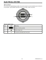
Page 26: ... panel is to provide electrical system information to the operator It gives detailed information in the form of pattern codes and number Konw the digital display No Icon Meaning 1 battery remaining capacity 2 total working hours 3 controller fault battery fault motor fault ELECTRICAL SYSTEM 1 3 2 ...

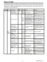
Page 27: ...tion Left or right drive controller overvoltage alarm No One long four short The battery voltage is too high Restart the machine if the fault persists send the machine to the designated after sales center for repair Left or go to drive controller undervoltage alarm No One long five short Battery pack power is low Charge the battery Abnormal communication alarm between left and right drive controll...

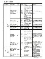
Page 28: ...ht drive motor is loose Go to the designated after sales center for check and repair The left drive controller and the right drive controller distinguish abnormal alarms No Two long five short 1 The 16pin connector between the vehicle wiring harness and the left controller is loose 2 The 16pin connector between the vehicle wiring harness and the right controller is loose Go to the designated after...

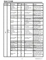
Page 29: ... Go to the designated after sales center for check and repair Operation sequence is abnormal No Three long three short 1 When the operator pushes forward the left steer control lever the right steer control lever is still on the park position 2 When the operator pushes forward the right steer control lever the left steer control lever is still on the park position During driving make sure that the...

Page 30: ...is recommended to operate at a suitable ambient temperature 20 c 55 c Excessive temperature differentials level 2 alarm Bms 23 No The internal temperature of the battery pack is seriously unbalanced After the whole machine is powered on again if the fault persists send the whole machine to the designated after sales point for repair Unit overvoltage level 2 alarm Bms 24 No The battery pack is over...

Page 31: ...e key to power efficiency and well groomed turf Keep them sharp a dull blade will tear rather than cut the grass leaving a brown ragged top on the grass within a few hours A dull blade also requires more power Replace any blade that is bent cracked or broken W A R N I N G Never attempt to straighten a bent blade by heating or weld a cracked or broken blade as the blade may break and cause serious ...

Page 32: ...ore reinstalling Lay the blade on a flat surface and check for distortion Replace any distorted blade W A R N I N G The blade sail curved part must be pointing upward toward the inside of the deck to ensure proper cutting W A R N I N G When mounting blades rotate them after installation to ensure blade tips do not touch each other or sides of the mower W A R N I N G Failure to correctly torque the...

Page 33: ...tach the charger adapter to the charging port and the batteries per the Charging Adapter section in the Electrical System section Plug the charger into a proper electrical outlet Refer to Battery Charger Battery Charging and Charging Recommendations portions of the Electrical System section for more details on using the charger and charging the batteries For additional information on battery stora...

Page 34: ...arged state or damage to the batteries will occur Charge batteries indoors in a well ventilated and dry location away from sparks or flames Never expose charger to rain vapor or liquid Charge only lithium batteries provided by Greenworks Do not touch uninsulated portion of charger terminal pins or of output connector Do not use with defective cords and wires Replace defective cords and wires immed...

Page 35: ...to move when the traction drive system is running and the drive wheels are rotating Use only certified jack stands Use only appropriate jack stands with a minimum weight rating of 2000 pounds 907 2 kg to block the unit up Use in pairs only Follow the instructions supplied with the vehicle stands Do not touch hot parts of machine Keep nuts and bolts tight especially the blade attachment bolts Keep ...

Page 36: ...I N G If the battery pack cracks or breaks with or without leaks do not recharge or use the battery Dispose of it and replace with a new battery pack DO NOT ATTEMPT TO REPAIR IT To avoid injury and risk of explosion or electric shock and to avoid damage to the environment Cover the battery s terminals with heavy duty adhesive tape DO NOT attempt to remove or destroy any of the battery pack compone...

Page 37: ...to the desired direction forward or backward Sudden breakdown during driving 1 The battery capacity is too low 2 The seat switch is disconnected on rugged and bumpy roads 3 The accelerator fails 4 The drive controller fails 5 The battery malfunctions 1 Please charge the machine 2 Make sure you sit in the seat after returning the left and right steer control levers to the neutral position push or p...

Page 38: ...way 1 Make sure the operator sits in the seat or the machine is shut down 2 Contact the after sales service center The machine cuts the grass unevenly and the front and back area differs a lot 1 The blade is very blunt 2 The cutter is bent 3 The deck is not even 1 Sharpen the blade according to the method in the manual 2 Wear protective equipment and replace the curved blade according to the instr...

Page 39: ...s 2 Please check the grass condition before cutting the grass If the grass is too wet please wait until it is dry or the lawn dew dissipates 3 Reduce the drive speed 4 Set the blade speed to high mode The machine running time is too short The grass is too heavy which shortens the cutting time Raise the deck height and reduce the blade speed can increase the cutting time in one round The machine is...

Page 40: ... of a digital multimeter on the positive battery terminal of the deck controller B Place the positive probe of the digital multimeter on deck controller terminals AR then CR Resistance for each should read between 270K Ω and 330k Ω If resistance is above or below the specified range the deck controller will need to be replaced Repeat process for deck controller terminals AL BL and CL 7 If no issue...

Page 41: ...in commercial applications are not covered by warranty This also includes no warranty on the batteries C Rental Use Greenworks Products used in rental applications are not covered by warranty This also includes no warranty on the batteries NOTE Failure to properly maintain batteries and keep them fully charged will reduce battery life and will void the battery warranty The provisions of this limit...

Page 42: ... or any unapproved modification to components electronics or software DISCLAIMER OF WARRANTY The foregoing warranties are in lieu of all other warranties expressed or implied including but not limited to the implied warranties of merchantability and fitness for a particular purpose However if the Greenworks product is purchased as a consumer product any implied warranty of merchantability or fitne...

Page 43: ...ny operator prior to using the Greenworks Commercial Product should thoroughly familiarize themself with the owner s manual regarding operation and safety of the machine as well as all safety warnings on the machine itself ALLOCATION OF RISKS This agreement allocates the risks of product failure between Greenworks and the Owner This allocation is recognized by both parties and is reflected in the ...

Page 44: ...Greenworks Tools PO Box 1238 Mooresville NC 28115 TOLL FREE HELPLINE 1 855 470 4267 Printed in China on 100 Recycled Paper ...

Reviews: