GREENSTAR 12Ri ErP Installation, Commissioning And Servicing Instructions Download Page 29

COMMISSIONING

Greenstar Ri 

ErP

 - 6 720 813 283 (2015/07)

29

6.2

FILLING THE SYSTEM

Open vented systems:
▶ Ensure all system and boiler drain points are closed.
▶ Open all radiator valves.
▶ Turn on the water supply to the system header tank and allow the 

system to fill.

Sealed systems:
▶ Fill the system via a WRAS approved filling loop to 1 bar then turn the 

valve anti-clockwise to close.

Opened vented and sealed systems:
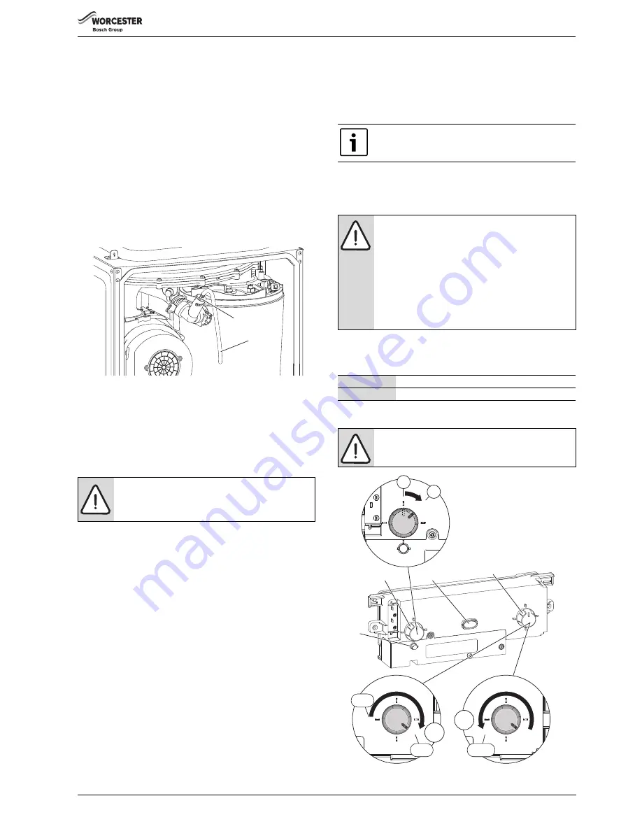
▶ Vent (1) any air from the boiler heat exchanger using a suitable 

container to collect any water. Ensure tube outlet (2) is directed away 
from the fan or any other electrical component to prevent any water 
damage. Also place a suitable cover over the fan to prevent any 
spillage of water on to electrical connections. Ensure the cover is 
removed after venting.

Fig. 40 Venting

▶ Vent all radiators and the primary side of the hot water cylinder, 

tighten when completed and check the system and correct any leaks.

Sealed systems only:
▶ If required increase system pressure back to 1 bar.
▶ Isolate and remove filling loop connection to system.

6.3

WATER TREATMENT

It is possible to have an ion exchange water softener fitted to the cold 
water system of the property. However, the boiler requires an untreated 
cold water connection taken from the mains supply, before the water 
softener, to the primary water filling point of the heating system.

Alternatively there are water softening/treatment devices that do not 
adjust or alter the pH levels of the water. With these devices it may not 
be necessary to provide an untreated water by-pass to the primary water 
filling point of the heat system.

ENSURE THAT THE SYSTEM HAS BEEN CLEANED AS ON PAGE 11 OF 
THESE INSTRUCTIONS

.

FLUSHING (Central Heating):

▶ Switch off the boiler.
▶ Open all drain cocks and drain the system while the appliance is hot.
▶ Close drain cocks and add a suitable flushing agent at the correct 

strength for the system condition in accordance with the 
manufacturer's instructions.

▶  Run the boiler/system at normal operating temperature for the time 

stated by the manufacturer of the flushing agent.

▶ Drain and thoroughly flush the system to remove the flushing agent 

and debris.

INHIBITOR (Central Heating):

▶ Check drain cocks are closed and all radiator valves are open before 

adding a suitable inhibitor compatible with aluminium (or combined 
inhibitor/anti-freeze if the system is exposed to freezing conditions) 
to the heating system water in accordance with the manufacturers 
instructions.

▶ Fill system as described in section 6.2 opposite.
▶ Set all controls to maximum.
▶ Record the date when the inhibitor was added to the system on the 

warrantee card.

WATER TREATMENT PRODUCTS

Suitable water treatment products can be obtain from the following 
manufacturers:

6.4

STARTING THE APPLIANCE

Fig. 41 Boiler controls

NOTICE: 

▶ ARTIFICIALLY SOFTENED WATER MUST NOT BE 

USED TO FILL THE CENTRAL HEATING SYSTEM.

6720804530-12.1Wo

1

2

The pH value of the system water must be less than 8 or 
the appliance warrantee will be invalidated.

NOTICE: 

▶ The concentration of inhibitor in the system should be 

checked every 12 months or sooner if system content 
is lost.

▶ Normally the addition of sealing agents to the system 

water is not permitted as this can cause problems 
with deposits left in the heat exchanger.

▶ In cases where all attempts to find a micro leak have 

failed, Worcester, Bosch Group supports the use of 
Fernox F4 leak sealer.

FERNOX

0870 601 5000 or www.fernox.com

SENTINEL

0800 389 4670 or www.sentinel-solutions.net

CAUTION: 

RUNNING THE APPLIANCE

▶ Never run the appliance when the appliance/system is 

empty or partially filled.

1

2

3

4

1.

0

1

1

0

MIN

RESET

MAX

max

min

2.

MIN

RESET

MAX

reset

3.

6720644744-30.1W

o

Summary of Contents for 12Ri ErP

Page 1: ...If you smell gas Well away from the building call the National Gas Emergency Service on 0800 111 999 L P G boilers Call the supplier s number on the side of the gas tank These appliances are for use w...

Page 2: ...lectrical connections 27 6 COMMISSIONING 28 6 1 Pre Commissioning checks 28 6 2 Filling the system 29 6 3 Water treatment 29 6 4 Starting the appliance 29 6 5 Commissioning 30 6 5 1 Checking the gas i...

Page 3: ...RTING INSTALLATION Warnings in this document are identified by a warning triangle printed against a grey background Keywords at the start of a warning indicate the type and seriousness of the ensuing...

Page 4: ...for more information Health and safety The appliance contains no asbestos and no substances have been used in the construction process that contravene the COSHH Regulations Control of Substances Haza...

Page 5: ...lies for domestic purposes EN12828 Central heating for domestic premises BS5440 1 Flues and ventilation for gas appliances of rated heating not exceeding 70kW net Flues BS5440 2 Flues and ventilation...

Page 6: ...1 Wall hung gas fired condensing regular boiler for central heating and domestic hot water 2 Tail pipes water only 3 Wall plate 4 Hardware literature pack see checklist 5 ErP Label 6 Bottom panel and...

Page 7: ...66 59 71 61 79 64 Flue gas temp 40 30 C rated min load C 41 33 44 33 48 34 54 35 43 35 46 36 49 37 55 38 CO2 level at max rated heat output after 30 min 9 65 9 8 9 8 9 8 11 0 11 0 11 0 11 0 CO2 level...

Page 8: ...regime means 60 C return temperature at heater inlet and 80 C feed temperature at heater outlet P4 kW 12 15 18 24 At 30 of rated heat output and low temperature regime 2 2 Low temperature means for c...

Page 9: ...urn temperature at heater inlet and 80 C feed temperature at heater outlet P4 kW 12 15 18 24 At 30 of rated heat output and low temperature regime 2 2 Low temperature means for condensing boilers 30 C...

Page 10: ...mbly 20 Syphon Trap 7 Overheat thermostat 21 Gas inlet connection 8 Silicon tube Heat Exchanger air vent 22 Mains cable inlet 9 Heat Exchanger 23 Gas Valve 10 Flue overheat thermostat 24 Flue air pres...

Page 11: ...3 phase supply IP20 Wiring must comply with the latest edition of BS 7671 IET wiring regulations 4 2 2 GAS SUPPLY To ensure that the equipment is in good working order and can meet the gasflowandpres...

Page 12: ...assisnotnecessaryonaYplansystem as one of the ports is open to flow 1 Static head Minimum static head 250mm measured from the highest point in the heating system top surface of the appliance or the hi...

Page 13: ...would be required to reach a suitable discharge point condensate should be removed using a proprietary condensate pump of a specification recommended by the boiler or condensate pump manufacturer The...

Page 14: ...chill at the open end The use of a drain cover such as those used to prevent blockage by leaves may offer further protection from wind chill Pipe drainage will be improved if the end is cut at 45 as o...

Page 15: ...ner can gain clear and safe access to the controls check top up or reset the appliance Products in loft cavities must have permanent fixed lighting a permanentfixedretractableladderandafixedfloorareas...

Page 16: ...space required to install and service the boiler inside an unventilated compartment CAUTION CLEARANCES Top and bottom clearances must not be reduced below the values shown in table 12 as they are the...

Page 17: ...mbing manifold Fig 19 Pipe work dimensions Heating System 22mm compression fittings Gas 22mm compression fittings Do not use the pre formed copper pipes supplied with the boiler for the gas supply The...

Page 18: ...hould be viewable from both directions NOTICE Effective flue lengths each90 bendisequivalentto2metresofstraightflue each 45 bend is equivalent to 1 metre of straight flue Plume management kits are ava...

Page 19: ...um flue length mm 60 100 80 125 High level horizontal flue with 2 x 90 bends 2 600 11 000 Table 23 Maximum flue length mm 60 100 80 125 High level horizontal flue with 3 x 90 bends N A 9 000 Table 24...

Page 20: ...tters pipe and drains 16 The dimension below eaves balconies and car ports can be reduced to 25mm as long as the flue terminal is extended to clear any overhang External flue joints must be sealed wit...

Page 21: ...00mm clearance 8 Clearances no less than 200mm from the lowest point of the balcony or overhang 9 1 200mm from an opening in a car port on the same wall e g door or window leading into the dwelling 10...

Page 22: ...d sleeve 6 5 Remove the plastic cover 7 Fig 25 Unpacking 2 Note Measurement M plume length Mmustbeaminimumof500mmandmustnotexceed 4 500mm for a 60mm plume management system used with the horizontal 60...

Page 23: ...levant safety precautions must be undertaken Protective clothing footwear gloves and safety goggles must be worn as appropriate FIXING THE MOUNTING FRAME Theboilertemplateshowstherelativepositionsofth...

Page 24: ...he appliance it is possible to fit the flow and return pipes supplied with the boiler installed on the wall If clearance is less than 600mm below the appliance it may be necessary to fit the flow and...

Page 25: ...n the fitting pack 1 Fit washer 1 inside the plastic nut and attach firmly to the connection on the syphon 2 Connect the condensate disposal pipe work to the elbow 2 refer to figure 31 and insert the...

Page 26: ...ptor kit are used to secure turret adaptor to the appliance Fig 33 Flue turret adaptor connection Additional notes and reminders Ensure that all cut lengths are square and free from burrs Ensure that...

Page 27: ...iler Demand from external wiring centre ST2 Connect SWITCHED LIVE wire to terminal LR Fig 35 Wiring detail NEW COMPLETE SYSTEM INSTALLATIONS Ifanewcomplete heatingsystemisinstalled inanewbuild propert...

Page 28: ...gas pipe work connections and rectify any leaks Check that the condensate pipe has been connected to the syphon Ensurethatthecondensatepipehasbeeninsertedatleast25mminto the elbow Fig 39 Condensate c...

Page 29: ...s and drain the system while the appliance is hot Close drain cocks and add a suitable flushing agent at the correct strength for the system condition in accordance with the manufacturer s instruction...

Page 30: ...en the screw in the inlet pressure test point 1 and connect a manometer Open gas isolation valve Measure the pressure with the boiler running at maximum Refer to section 7 4 to set the boiler to maxim...

Page 31: ...heck flow chart NOTICE BEFORE CO AND COMBUSTION CHECKS Refer to section 6 5 1 and 6 5 2 to verify gas type gas inlet pressure and gas rate Visually check the integrity of the whole flue system and con...

Page 32: ...n Commissioning and Service manual with the Benchmark checklist and service record is left with the boiler or homeowner Iftheapplianceisunusedandexposedtofreezingconditions shutoff all the mains suppl...

Page 33: ...t Finding on page 48 for rectification procedures COMPONENT ACCESS Removing outer case 1 Undo and remove two screws securing boiler casing at the top of the appliance 2 Undo but do not remove the two...

Page 34: ...Fig 51 Flue integrity test 7 4 FAN PRESSURE TEST SETTING THE BOILER TO MAXIMUM 1 Remove the three screws retaining the control cover 2 Remove the control cover 3 Remove the plastic tool clipped inside...

Page 35: ...7 5 FLUE GAS ANALYSIS COMBUSTION TEST Connect the flue gas analyser to the flue gas sampling point as shown in the figure below Run the boiler at maximum output for at least 10 minutes Check the CO CO...

Page 36: ...taining plate assembly Fig 59 Securing nut NOTICE THE SETTING OF THE GAS RATIO MUST BE CARRIED OUT BY A COMPETENT PERSON SETTING OF THE GAS RATIO MUST NOT BE ATTEMPTED UNLESS THE PERSON CARRYING OUT T...

Page 37: ...d cleaning the electrode assembly Inspect the condition of the electrodes and ceramics replace if necessary Use a plastic scouring pad to clean the electrodes BAFFLE REMOVAL 1 Refer to figure 62and re...

Page 38: ...AND CLEANING To release the syphon from the sump 1 Undo the plastic nut on the bottom of the syphon and move the condensate pipe away from the syphon 2 Remove the two screws retaining the syphon brac...

Page 39: ...lace 7 8 3 OVERHEAT THERMOSTAT Refer to figure 68 for removal Remove two electrical connectors from thermostat 3 Slacken and remove fixing screw and thermostat 3 When replacing ensure thermostat sits...

Page 40: ...flue limit thermostat in from the sump Retrieve the thermostat from the sump well Fig 70 Remove thermostat To replace push the thermostat and new grommet gently back into the opening until contact wi...

Page 41: ...sembly 1 around the top of the heat exchanger until the lug on the air gas manifold is visible Lift up assembly and remove from boiler Fig 75 Rotate the air gas manifold assembly NOTICE The valve will...

Page 42: ...the screw holding the retaining plate 4 Remove the retaining plate 5 Remove three screws and the mixing chamber Re assemble with new fan ensuring seals are correctly fitted Fig 78 Dismantling the air...

Page 43: ...lamping plate and the top of the heat exchanger refer to figure 81 Fig 81 Initial location of the clamping plate 1 Retaining plate assembly 2 Clamping plate 3 Gasket 4 Bracket 5 Underside view of the...

Page 44: ...anti clockwise to release from the hook 3 Pull the upper exhaust connector down Fig 85 Upper exhaust assembly 1 Refer to figure 86 and release the clip 2 Move the lower exhaust connector up Remove the...

Page 45: ...ket 2 The code plug should be left attached to the frame of the boiler by its plastic safety thread 7 8 17 TRANSFORMER PCB To change either the PCB F2 fuse or transformer Remove two screws securing th...

Page 46: ...board Re assemble in reverse order NOTICE CODE PLUG Ensure that the code plug is fitted to the new control The appliance will indicate an error and will not function correctly NOTICE CO CO2 After com...

Page 47: ...burner WB6 8 716 110 534 0 Seal Inner case mantel 8 716 106 635 0 H26 545 Flow temperature sensor NTC 8 716 106 688 0 GC No H26 542 Air pressure switch 8 716 106 633 0 G C No H26 543 Seals kit 8 716...

Page 48: ...t ST2 terminal LR is there a demand Manual bypass is open If CH is working check HW controls If HW is working check CH controls i e external diverter valve frost stat room stat programmer Otherwise re...

Page 49: ...fuse AC 230 V Slow T1 25 A fuse CH TEMPERATURE CONTROL PRESSURE SWITCH 230V WIRING CENTER JUNCTION BOX FAN Colour sequence SL L N Min Max Norm ON OFF SWITCH 230V AC 25V Red Blue Violet Orange Live Ne...

Page 50: ...CKOUT 45 second stabilisation period Fan modulation to achieve set temperature 40 82 C END OF BOILER DEMAND Gas valve OFF Pump run 3 minutes Fan run 30 seconds Over temperature shut down if water temp...

Page 51: ...overrun period Internal boiler temperature rises above 12 C Central heating demand switches off Pump switches off after a 3 minute overrun period Central heating demand is activated Pump runs for 3 mi...

Page 52: ...Greenstar Ri ErP 6 720 813 283 2015 07 52 NOTES...

Page 53: ...Greenstar Ri ErP 6 720 813 283 2015 07 53 NOTES...

Page 54: ......

Page 55: ......

Page 56: ...orcester Bosch Group is a brand name of Bosch Thermotechnology Ltd worcester bosch co uk 6 720 813 283 2015 07 WORCESTER BOSCH GROUP TECHNICAL SUPPORT 0330 123 3366 APPOINTMENTS 0330 123 9339 SPARES 0...

Reviews: