12
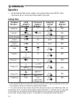
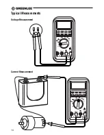
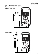
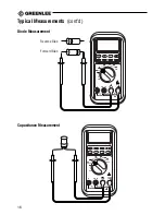
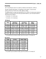
Settings Table
To measure
set the
this icon will
connect the
and the
this value …
selector to
appear on
red lead
black lead
this symbol …
the display …
to …
to …
Capacitance*
F
Temp
COM
Ω
V
Continuity**
Ω
and
Ω
Temp
COM
and press SELECT
Ω
V
Current (10A max)
A
A
A
COM
Current
mA
mA
µ
AmA
COM
(500 mA max)
Current
µ
A
µ
A
µ
AmA
COM
(5000
µ
A max)
Diode
Temp
COM
and
Ω
V
and press SELECT
V
Frequency
Hz
Temp
COM
V
Ω
V
and press Hz
Resistance***
Ω
Ω
Temp
COM
Ω
V
and V
V
Temp
mV
and mV
Ω
V
COM
and press SELECT
and V
V
Temp
COM
mV
and mV
Ω
V
Temperature
Temp
C or F
Temp
COM
(press SELECT
Ω
V
to change scale)
Voltage (AC)
Voltage (DC)
* Discharge capacitor before measurement. Discharge a large capacitor through an appropriate resistive load.
** Tone indicates continuity. The threshold is between 20
Ω
and 200
Ω
.
*** For precise resistance measurements, begin in the autoranging mode and press RANGE twice. When the
meter displays “Shrt”, short the test leads together until the meter reads “0”. The meter will now compensate
for the resistance of the test leads and the internal protection circuitry, allowing very precise resistance
measurements. Changing ranges, functions, or going back to autoranging mode will reset the meter.
Operation
1.
See the Settings Table. Set the selector to the proper setting, press SELECT (when
instructed to do so), and connect the test leads to the meter.


