background image

41

VersiVent Energy Recovery Ventilator

Troubleshooting - Economizer 

Alarms

Addressing Alarms

Alarms will signify a faulty sensor. When this occurs, 
verify all connections to the sensor and controller are 
secure. Press enter twice to clear the alarm. If the issue 
persists, consult the factory.

Clearing Alarms

Once the alarm has been identified and the cause has 
been removed (e.g. replaced faulty sensor), the alarm 
can be cleared from the display.
To clear an alarm, perform the following:
1.  Navigate to the desired alarm.
2.  Press the   (enter).
3.  ERASE? displays.
4. Press   (enter).
5.  ALARM ERASED displays.
6. Press   (escape) to complete the action and return 

to the previous menu.

NOTE

If an alarm still exists after you clear it, it redisplays 
within 5 seconds.

Reference

Technical Support

For technical support contact the Tempered Air 
Products group from Monday - Friday, 8AM-5PM CST 
at 1-877-202-6123. 
Refer to the following Installation, Operation and 
Maintenance Manuals for additional details. All are 
available at www.greenheck.com
•  Centrifugal Fan
•  PVF/PVG Indirect Gas-Fired Heat Modules
•  Microprocessor Controller

Summary of Contents for VersiVent VER-45

Page 1: ...ical and safety codes as well as the National Electrical Code NEC the National Fire Protection Agency NFPA where applicable Follow the Canadian Electric Code CEC in Canada 2 All moving parts must be free to rotate without striking or rubbing any stationary objects 3 Unit must be securely and adequately grounded 4 Do not spin fan wheel faster than maximum cataloged fan RPM Adjustments to fan speed ...

Page 2: ...cupied Recirculation Damper 19 Service Outlet 19 Vapor Tight Lights 19 Hot Gas Bypass Valve 19 Hot Gas Reheat Valve 19 Digital Scroll Compressor 19 Cooling System Overview Packaged DX 20 Start Up Warnings 21 Special Tools Required 21 Start Up Procedure 21 Voltage Imbalance 21 Pre Start Up Checklist 22 Start Up Checklist 22 23 Optional Accessories Checklist 24 Start Up Components Energy Wheel 25 Fa...

Page 3: ...n wheel bearings drive motor base and accessories for tightness 2 Rotate the fan wheel s by hand and assure no parts are rubbing Receiving Upon receiving the product check to make sure all items are accounted for by referencing the bill of lading to ensure all items were received Inspect each crate for shipping damage before accepting delivery Notify the carrier if any damage is noticed The carrie...

Page 4: ... part of the exhaust hood assemblies Motorized outdoor air and return air dampers are optional and are factory mounted and wired at the intake Hot Water Chilled Water Coils Water coils can be used for a single purpose such as heating or cooling or their function can be alternated between heating and cooling by changing the temperature of the water flowing through the coil Depending on the applicat...

Page 5: ...ction Optional Condensing Section C o n d e n s i n g C o i l Drain Pan Connection IG Gas Connection AN W TION W Plan View Unit Size A B C D E F G H I W L Weight lbs D1 D2 D3 D4 VER 45 16 381 28 146 44 627 30 159 36 159 44 159 50 275 36 312 47 571 63 964 65 851 18 780 69 987 see note 4900 VER 65 16 381 30 825 46 597 30 159 36 159 44 159 50 275 38 124 47 571 65 958 72 098 23 358 76 246 6300 VER 90 ...

Page 6: ...t CW Chilled Water HP Wrap around Heat Pipe DX Direct Expansion HGRH Hot Gas Reheat Elevation View W 3 75 inches L 3 75 inches Subtract 3 75 inches from dimensions W L to get the outside curb dimensions Most factory supplied electrical components are pre wired To determine what electrical accessories require additional field wiring refer to the unit specific wiring diagram located on the inside of...

Page 7: ... of this unit Hot air is being discharged through the condensing fans during operation and the more clearance available the better the chance of avoiding recirculation or coil starvation This unit should never be placed under an overhang or inside a building A minimum of 48 inches over the condensing fans is recommended Minimum 24 inches clearance Condensing Coil Intake Keep this area clear Minimu...

Page 8: ...air intake damper optional Outdoor air filters Frost control sensors optional Economizer sensors optional 5 Coil access drain pan final filters Bypass damper optional 6 Control center All electrical controls VFD for energy recovery wheel optional 7 Indirect gas furnace control center 8 Supply air fan motor and drives with indirect gas furnace Electric post heater control center optional 9 Compress...

Page 9: ... 10 3 VER 90 A B C D E F G H 1 77 9 4 7 99 2 15 9 33 8 61 9 2 0 12 7 2 77 9 4 7 99 2 15 9 33 8 51 9 7 5 17 7 3 77 9 4 7 99 2 15 9 33 8 51 9 35 3 17 7 4 77 9 4 7 99 2 15 9 33 8 61 9 29 9 12 7 All dimensions are in inches IG Indirect Gas Furnace PDX Packaged DX Cooling 1 Any unit without IG and PDX Blower Module is at the end of the unit 2 Any unit with IG that does not have PDX 3 Any unit with IG a...

Page 10: ... unit 4 Set the Unit Lift unit to a point directly above the curb and duct openings Guide unit while lowering to align with duct openings Roof curbs fit inside the unit base Make sure the unit is properly seated on the curb and is level A B C D Return Air Intake Supply Air Discharge Unit A B C D VER 45 53 3 16 33 8 w IG 27 w o IG 9 2 IG w o CS 37 1 IG w CS 5 2 w o IG and CS 33 1 w o IG and w CS VE...

Page 11: ...50 x 31 50 x 31 60 VER 90 62 x 34 59 7 x 35 60 All dimensions shown in inches See diagram in Recommended Roof Openings section for the Bottom Discharge opening sizes Recommended Exhaust Fan Discharge Duct Size Unit Duct Size Exhaust Blower Size Length of Straight Duct Exhaust Fan VER 45 20 x 20 12 48 VER 65 28 x 28 15 60 VER 90 32 x 32 18 60 All dimensions shown in inches Recommended duct sizes ar...

Page 12: ... the Size of Electric Heater Wiring An optional electric heater may require a separate power supply The power connection should be made to the factory provided electric heater disconnect and must be compatible with the ratings on the nameplate supply power voltage phase and amperage Consult ANSI NFPA 70 and CSA C22 1 for proper conductor sizing 3 Provide the Opening s for the Electrical Connection...

Page 13: ...four feet of service room between the switch and system access panels When providing or replacing fuses in a fusible disconnect use dual element time delay fuses and size according to the rating plate Discharge Air Temperature Sensor Without Indirect Gas Furnace For units without an indirect gas furnace the discharge air temperature sensor is factory mounted in the blower discharge section of the ...

Page 14: ...S EXHAUST DIRTY FILTER SWITCH SUPPLY DIRTY FILTER SWITCH HOT COMMON Dirty Filter Indicator Powered by others A W1 12 7 6 Y2 Y1 G C R UNIT ON OFF COOL STAGE 1 ECONOMIZER COOL STAGE 2 UNOCCUPIED RECIRCULATION S1 S6 S7 S4 S5 HEAT UNIT INTERFACING TERMINALS TERMINAL BLOCKS IN UNIT CONTROL CENTER Unit Interfacing Terminals Heating Cooling Switches and Night Setback Switch Timer W1 12 7 6 Y2 Y1 G C R NC...

Page 15: ...nce 3 Water coils are not normally recommended for use with entering air temperatures below 40 F No control system can be depended on to be 100 safe against freeze up with water coils Glycol solutions or brines are the only safe media for operation of water coils with low entering air conditions If glycol or brine solutions are not used coils must be drained when freezing conditions are expected I...

Page 16: ...ded with the P trap If local and area codes permit the condensate may be drained back onto the roof but a drip pad should be provided beneath the outlet If local and area codes require a permanent drain line it should be fabricated and installed in accordance with Best Practices and all codes In some climates it will be necessary to provide freeze protection for the P trap and drain line The P tra...

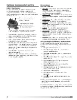
Page 17: ...turn Air 75 F 50 RH Exhaust Air Outdoor Air 10 F 5 grains lb Supply Air 60 F 39 grains lb Return Air 72 F 40 RH Optional Component Overview Economizer The energy wheel operation can be altered to take advantage of economizer operation free cooling Two modes are available 1 Stopping the wheel 2 Modulating the wheel Stopping the wheel A field supplied call for cool Y1 is required De energizing the w...

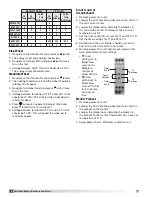
Page 18: ...air temperature is less than 5 F AND the pressure differential is greater than the set point the wheel will run at reduced speed until the pressure differential falls below the set point The VFD will be fully programmed at the factory Variable Frequency Drives VFD Variable frequency drives are used to control the speed of the fan as either multi speed or modulating control Multi speed VFDs referen...

Page 19: ...equipped with a reheat coil use a three way valve with actuator to control the supply air discharge temperature of the unit during dehumidification mode The unit controller provides a 0 10 VDC signal to control the amount of reheat to meet the supply temperature set point Digital Scroll Compressor PDX Only Refrigeration Modulation Digital scroll compressors modulate the refrigeration system increa...

Page 20: ...f reheat to meet the supply temperature set point 4 Hot Gas Reheat Coil 5 Hot Gas Reheat Check Valve 6 Condenser Fans 7 Condensing Coil 8 Liquid Receiver optional 9 Sight Glass 10 Liquid Line Filter Drier 11 Thermostatic Expansion Valve TXV Each unit is equipped with a TXV on each refrigerant circuit The valve controls the flow of liquid refrigerant entering the evaporator coil by maintaining a co...

Page 21: ...en on cycles to prevent compressor damage Prior to starting up the unit power must be energized for 24 hours without a call for cooling to allow the compressor crankcase heaters time to boil off any liquid refrigerant present in the compressor DX system is charged with refrigerant Start up must be performed by EPA Certified Technician SPECIAL TOOLS REQUIRED Voltage Meter with wire probes Amperage ...

Page 22: ... fan wheels and energy recovery wheels by hand and ensure no parts are rubbing o Check the fan belt drives for proper alignment and tension o Filters can load up with dirt during building construction Replace any dirty pleated filters and clean the aluminum mesh filters in the intake hood o Verify that non motorized dampers open and close properly o Check the tightness of all electrical wiring con...

Page 23: ...ting Cooling Cooling HP Heating A Discharge Pressure B Discharge Pressure Converted to Temperature C Liquid Line Temperature D Subcooling B C Should be between 12º and 17ºF E Suction Line Pressure F Suction Line Temperature G Suction Pressure Converted to Temperature H Superheat F G Should be between 8º and 12ºF Water In Water Out Hot Gas Bypass Operational Not present on digital scroll compressor...

Page 24: ...EA Dirty Filter Sensor Yes No N A Yes No CO2 Sensor Yes No N A Yes No Service Outlet Yes No N A Yes No Vapor Tight Lights Yes No N A Yes No Remote Control Panel Yes No N A Variable Frequency Drives Section Operational Yes No Blower VFDs Yes No N A Yes No Wheel VFD Yes No N A Damper Section Operational Yes No Outdoor Air Damper Yes No N A Yes No Exhaust Air Damper Yes No N A Yes No Night Setback Da...

Page 25: ...als Push the wheel cassette back into the unit and plug in the power connector Turn the main power supply back on and then observe the operation of the wheel by opening the wheel access door slightly Remove filters if necessary to observe the wheel Label showing cassette serial number and date code Bearing Support Drive Pulley Adjustable Air Seals Drive Belt Bearing Support Bar Showing air seal as...

Page 26: ...f the motor pulley Multi groove variable pitch pulleys must be adjusted an equal number of turns open or closed Any increase in fan speed represents a substantial increase in load on the motor Always check the motor amperage reading and compare it to the amperage rating shown on the motor nameplate when changing fan RPM All access doors must be installed except the control center door Vibration Ex...

Page 27: ...an Set point menu default 53 F 2 LOW T LOCK The set point for the low temperature mechanical cooling lockout Set point menu default 32 F 3 DRYBLB SET The outdoor air set point to call for economizer Set point menu default 63 F 4 MIN POS The minimum signal voltage sent to the energy wheel This must be set to 2 VDC Set point menu default 2 8 VDC 5 AUX1 O The controllers operating sequence structure ...

Page 28: ...sc has a pre set temperature of 5 F 4 Apply power to unit Preheater should turn on Stop Wheel 1 Navigate to the Checkout menu and press enter 2 The energy wheel and cooling should stop 3 Navigate to Connect ERV and press enter twice to run the test 4 Voltage between AUX1 O and C should be 24 VAC The energy wheel should activate Modulate Wheel 1 Navigate to the Checkout menu and press Enter 2 The c...

Page 29: ... is now reset back to the settings programmed at Greenheck This option is not available on the J1000 MA MB MC RP H1 SC HC S7 S6 S5 S4 S3 S2 S1 MP AC AM AC V A2 A1 PC P2 P1 IG S S R R V1000 MA MB MC AC AM AC V A1 SC S5 S4 S3 S2 S1 J1000 OPTION 1 0 10 VDC CONTROL SEE VFD INSTALLATION MANUAL FOR MORE DETAIL USER TO PROVIDE ISOLATION AS REQUIRED FOR CONTINUOUS 60Hz OPERATION JUMPER TERMINALS A1 AND V ...

Page 30: ...ction 5 5 H3 10 A2 Not Used F NA L4 01 H2 01 Frequency Detection 15 15 L5 01 Auto Restart Attempt 5 5 A1 01 Access Level 0 0 Variable Frequency Drives for Energy Recovery Wheel Parameter Setting J1000 A1 01 Access Level 2 B1 17 VFD Auto Start 1 C1 04 Decel Time 600 C4 01 Torque Gain 0 6 C6 02 Carrier Frequency 2 D2 01 Ref Upper Limit 40 or 50 D2 02 Ref Lower Limit 5 E2 01 Motor Rated FLA Motor FLA...

Page 31: ...iate for the installation The following is provided as a guideline Maintenance Frequency Monthly 1 External Filter Clean metal mesh filters 2 Internal Filters Replace MERV 8 filters monthly Adjust replacement schedule for MERV 13 or other filters as inspection requires Semiannually 1 Check motor and motor bearings Check for excessive heat vibration or noise Lubricate bearings in accordance with th...

Page 32: ...occur should be one inch using moderate thumb pressure at mid point of the drive Check belt tension two times during the first 24 hours of operation and periodically thereafter Fan Motors Motor maintenance is generally limited to cleaning and lubrication Cleaning should be limited to exterior surfaces only Removing dust and grease buildup on the motor housing assists proper cooling Never wash down...

Page 33: ...nd if dirty brush or vacuum clean Soiled fins reduce the capacity of the coil demand more energy from the fan and create an environment for odor and bacteria to grow and spread through the conditioned zone For coils with fragile fins or high fin density foaming chemical sprays and washes are available Care must be taken not to damage the coils including the fins while cleaning Caution Fin edges ar...

Page 34: ...y should be closed as soon as possible If the wheel should rotate when a clip is open the clip will jam against the bearing support bar and could cause damage Cleaning Maintenance or cleaning of the wheel segments should be done with the segments removed from the wheel cassette to avoid splashing liquids or cleaning agents inside the cabinet If the energy wheel appears excessively dirty it should ...

Page 35: ...atalog for fan curves to determine if horsepower is sufficient Shorted windings in motor Replace motor Low airflow cfm Unit damper not fully open Adjust damper linkage or replace damper motor System static pressure too high Improve ductwork to eliminate losses using good duct practices Blower speed too low Check maximum motor RPM and compare with catalog data Verify that external control wiring is...

Page 36: ...place fuse after correcting problem Low line voltage Check line voltage If more than 10 from compressor marking correcting is necessary Compressor motor protector open Motor thermal protector automatically resets Allow time two hours for compressor to cool down so protector will reset Restart and check for reason overheat occurred Compressor defective Check motor for open circuit short circuit gro...

Page 37: ...ad If compressor is hot allow compressor to cool for two hours Recheck for open circuit Improper refrigerant charge Check subcooling Improperly wired Review wiring schematics Loose wiring Check all connections Defective start relay Replace relay Motor windings damaged Verify amp draw Compressor hums but will not start Improperly wired Review wiring schematics Low line voltage Check voltage Loose w...

Page 38: ...oil Condenser fan not running or running backwards Check electrical circuit and fuse Check fan cycling controls High load conditions Add more equipment or reduce load Low suction pressure Refrigerant undercharge loss of refrigerant charge Check pressures and subcooling Blower running backward Confirm blower rotation If reversed interchange any two wires from 3 phase disconnect Low entering air tem...

Page 39: ...rature Restriction in suction and liquid line Check for restrictions in refrigerant circuit Control contacts stuck Check wiring Excessive load Add more equipment or reduce room load Liquid line is frosted or wet Restriction in liquid line Clear restriction upstream of point of frosting Suction line is frosting Insufficient evaporator airflow Check airflow check filters check VFD control signal for...

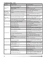
Page 40: ...gle function within the unit Microprocessor Controller Check the screen on the microprocessor for an alarm condition If it is in alarm condition a message will show on the screen The microprocessor controller is located in the main control center If it is in alarm condition the alarm button will blink red Press the alarm button to see the specific condition or to reset the microprocessor Refer to ...

Page 41: ...lear an alarm perform the following 1 Navigate to the desired alarm 2 Press the enter 3 ERASE displays 4 Press enter 5 ALARM ERASED displays 6 Press escape to complete the action and return to the previous menu Note If an alarm still exists after you clear it it redisplays within 5 seconds Reference Technical Support For technical support contact the Tempered Air Products group from Monday Friday ...

Page 42: ...and exhaust air filter racks for 2 inch MERV 8 30 efficient 7 Optional Final Filters 2 inch MERV 8 30 efficient 4 inch MERV 11 65 efficient 4 inch MERV 13 85 efficient 9 3 2 4 6 5 8 10 12 11 1 7 8 Coil section optional equipment Not all items depicted above Packaged or split DX cooling coil DX Hot gas reheat coil HGRH Chilled water coil CW Wrap around heat pipe HP Hot water coil HW Electric heat E...

Page 43: ...____________________________ _________________________________________________ _________________________________________________ Date____________________Time______________ AM PM Notes ____________________________________________ _________________________________________________ _________________________________________________ _________________________________________________ _____________________...

Page 44: ...Library under Warranties Greenheck catalog VersiVent provide additional information describing the equipment fan performance available accessories and specification data Phone 715 359 6171 Fax 715 355 2399 Parts 800 355 5354 E mail gfcinfo greenheck com Website www greenheck com Our Commitment AMCA Publication 410 96 Safety Practices for Users and Installers of Industrial and Commercial Fans provi...

Reviews: