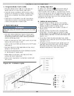
Green Mountain GM90-100 Installation, Operation And Maintenance Manual Download Page 28

28

Check Gas Supply

Gas pipe to your boiler must be correct size for length of 

run and for total Btu per hour input of all gas utilization 

equipment connected to it. See Table 7, Page 29. 
Boiler and its individual shutoff valve must be disconnected 

from gas supply piping system during any system pressure 

testing at test pressures in excess of ½ psig (3.5kpa).
Boiler must be isolated from gas supply piping system 

by closing its individual manual shutoff valve during 

any pressure testing of gas supply piping system at test 

pressures equal to or less than ½ psig (3.50ka).

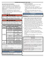
Table 6 - Gas Supply Pressure

NATURAL 

GAS

PROPANE 

GAS

Maximum Gas Supply  

Pressure

10” w.c.

14” w.c.

Minimum Gas Supply 

Pressure

4” w.c.

10” w.c.

GAS SUPPLY PIPING

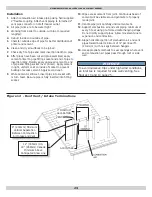
Connecting The Gas Piping

See Figure 19, Page 29 for general layout at boiler. 

Gas line enters boiler from right side jacket panel. 

Boiler is equipped with ½” NPT connection on gas valve for 

supply piping. 
Following rules apply:

1. 

Use piping materials and joining methods acceptable 

to authority having jurisdiction.  In absence of such 

requirements:

• USA - National Fuel Gas Code, ANSI Z223.1/NFPA 54
• Canada - Natural Gas and Propane Installation Code, 

CAN/CSA B149.1

2. 

Size and install gas piping system to provide sufficient 

gas supply to meet maximum input at not less than 

minimum supply pressure. See Table 7, Page 29

3. 

Use ground joint unions.

4. 

Provide sediment trap up stream of gas valve.

5. 

Use two pipe wrenches when making the connection to 

gas valve to keep it from turning.

6. 

Install a manual shutoff valve in the vertical pipe about 

5 feet above floor. 

7. 

Tighten all joints securely.

8. 

Propane gas connections should only be made by 

licensed propane installer.

9. 

Two stage regulation should be used by propane 

installer.

10. 

Propane gas piping should be checked out by propane 

installer.

CAUTION

WHAT TO DO IF YOU SMELL GAS

• Do not try to light any appliance.
• Do not touch any electrical switch; do not use 

any phone in your building.

• Immediately call your gas supplier from a 

neighbor’s phone.  Follow gas supplier’s 

instructions. 

• 

If you cannot reach your gas supplier, call the fire 

department.

!


DANGER

Fire Hazard.  Do not use matches, candles, open 

flames, or other methods providing ignition source. 

Failure to comply will result in death or serious        

injury.

!


Leak Check Gas Piping

Pressure test boiler and gas connection before placing 

boiler in operation.

• Disconnect boiler and its individual gas shutoff 

valve from gas supply system.

• Isolate boiler from gas supply system by closing 

manual gas shutoff valve. See Figure 19, 

Page 29.

• Locate leakage using gas detector, noncorrosive 

detection fluid, or other leak detection method 

acceptable to authority having jurisdiction.  Do 

not use matches, candles, open flames, or other 

methods providing ignition source.

• Correct leaks immediately and retest.

Summary of Contents for GM90-100

Page 1: ...T VENT CONDENSING HOT WATER BOILER INSTALLATION OPERATIONS AND MAINTENANCE MANUAL Manufactured by ECR International Inc 2201 Dwyer Avenue Utica NY 13501 web site www ecrinternational com Tested For 10...

Page 2: ...2 DIMENSIONS Figure 1 Boiler Dimensions NOTICE Draft inducer blower may be rotated 90 or 180 to orient vent connection towards right side or rear...

Page 3: ...nt Pipe 22 Gas Supply Piping 28 Electrical Wiring 30 Controls And Accessories 34 Start Up 36 Operating Instructions 37 Detailed Sequence Of Operation 38 Verification Procedure And Adjustment 42 Differ...

Page 4: ...nd Cleaning on page 47 NOTICE Used to address practices not related to personal injury CAUTION Indicates a hazardous situation which if not avoided could result in minor or moderate injury WARNING Ind...

Page 5: ...presents portion of remaining heat that can be applied to heat radiation or terminal units i e finned tube baseboard cast iron radiators radiant floor etc The difference between Heating Capacity and N...

Page 6: ...exception of 90 75 propane LP product are factory equipped for operation at altitudes ranging from 0 10 000 feet above sea level No changes to factory settings are required for installations from 0 5...

Page 7: ...model 90 75 Propane units only at altitudes above 5 000 ft install 90 75 High Altitude Orifice Kit 550002629 For all other altitudes use sea level orifice MODEL 90 100 Stock Factory Btu Value of Propa...

Page 8: ...or commercial applications any additional code requirements must be adhered to for installation This may require additional controls including but not limited to an additional low water cut off a manu...

Page 9: ...mit flow through piping systems without restrictions for boiler operation 8 Install boiler such that the automatic gas ignition system components are protected from water dripping spraying rain etc du...

Page 10: ...ny unused openings in the common venting system 2 Visually inspect the venting system for proper size and horizontal pitch and determine there is no blockage or restrictions leakage corrosion and othe...

Page 11: ...or pH reading outside acceptable range between 7 0 and 8 0 are indications the system should be cleaned or treated Thoroughly flush system with clean water to remove any sediment or contaminants Slud...

Page 12: ...12 NEAR BOILER PIPING Figure 2 Single Zone Boiler Piping SAFETY RELIEF VALVE SEE PAGE 18 FOR REQUIREMENTS...

Page 13: ...th very low heat and flow requirements compared to full heating capacity of the boiler This can result in very low flow in the boiler if only one small zone is calling for heat Primary Secondary Pipin...

Page 14: ...14 Figure 4 Two Zone Boiler Piping With Circulators NEAR BOILER PIPING SAFETY RELIEF VALVE SEE PAGE 18 FOR REQUIREMENTS...

Page 15: ...15 NEAR BOILER PIPING MAX 4 X DIAMETER CLOSELY SPACED TEES BOILER PUMP Figure 5 Primary Secondary Piping With Circulators And Domestic Hot Water...

Page 16: ...VE FOR OPTIMUM TANK PERFORMANCE CONSIDER USING ZONE CIRCULATOR BOILER PUMP MAX 4 X DIAMETER CLOSLEY SPACED TEES NEAR BOILER PIPING Figure 6 Piping Primary Secondary Multi Zone System Piping With Zone...

Page 17: ...17 NEAR BOILER PIPING ZONE VALVE MAX 4 X DIAMETER CLOSELY SPACED TEES Figure 7 Piping Primary Secondary Piping With Zone Valves And Domestic Hot Water With Circulator...

Page 18: ...e pipe with plain end not threaded Expansion Tank And Make Up Water Determine required system fill pressure system design temperature and system water content Boiler contains 2 6 gallons U S Size expa...

Page 19: ...19 Figure 9 Diaphragm Type Expansion Tank Piping NEAR BOILER PIPING SAFETY RELIEF VALVE SEE PAGE 18 FOR REQUIREMENTS...

Page 20: ...20 Figure 10 Conventional Closed Type Expansion Tank Piping NEAR BOILER PIPING SAFETY RELIEF VALVE SEE PAGE 18 FOR REQUIREMENTS...

Page 21: ...st be manually filled with water Following are the steps required to initially fill condensate trap for start up Steps are only required at initial start up or if maintenance requires draining of cond...

Page 22: ...vailable for visual inspection Specified primers and glues of certified vent system must be from single manufacturer and not intermixed with other manufacturer s vent system parts Components of the ce...

Page 23: ...ate at least 3 ft 0 9m above any forced air inlet except boiler s combustion air inlet within 10 ft 3m COMBUSTION AIR AND VENT PIPE Table 5 Combustion Air And Vent Piping Lengths Total Equivalent Leng...

Page 24: ...is still wet insert pipe into socket with turn twist Be sure pipe is fully inserted into fitting socket COMBUSTION AIR AND VENT PIPE VENT AIR INTAKE 12 305mm 18 12 305mm US 18 458mm Canada Minimum Ab...

Page 25: ...CLEAR ABOVE HIGHEST SNOW LEVEL OR GRADE 12 SEPARATION BETWEEN BOTTOM OF AIR INTAKE AND BOTTOM OF VENT 12 MINIMUM OVERHANG 3 MAXIMUM SEPARATION 12 MINIMUM 12 MINIMUM 12 MINIMUM 12 MINIMUM 36 MIN 36 MIN...

Page 26: ...a 18 457mm clearance above highest anticipated snow level or grade 12 305mm Minimum Must be less than 4 102mm or greater than 24 610mm Horizontal distance between end bells of each air intake to preve...

Page 27: ...equivalent length for all models TRANSITION FITTING 2 50 8mm to 3 76 2mm IN VERTICAL RUN 3 76 2mm Diameter Vent And Combustion Air Intake Piping 92 ft 28m maximum total equivalent length for 90 100 m...

Page 28: ...ly pressure See Table 7 Page 29 3 Use ground joint unions 4 Provide sediment trap up stream of gas valve 5 Use two pipe wrenches when making the connection to gas valve to keep it from turning 6 Insta...

Page 29: ...45 000 60 50 000 105 000 195 000 365 000 PROPANE GAS Length of Pipe Ft Pipe Capacity BTU Per Hour Input Includes Fittings Copper Tubing Iron Pipe 5 8 3 4 1 2 3 4 20 131 000 216 000 189 000 393 000 40...

Page 30: ...em Follow instructions included with your thermostat Locate thermostat about five feet above floor on inside wall Mount directly on wall or on vertical mounted outlet box It should be sensing average...

Page 31: ...31 Figure 20 Field Wiring Connections ELECTRICAL WIRING SAFETY RELIEF VALVE SEE PAGE 18 FOR REQUIREMENTS...

Page 32: ...32 ELECTRICAL WIRING Figure 21 Wiring Schematic NOTICE If any of original wire as supplied with this appliance must be replaced it must be replaced with type 105 C Thermoplastic wire or its equivalent...

Page 33: ...33 Figure 22 Ladder Diagram for Figure 22 ELECTRICAL WIRING...

Page 34: ...d boiler temperature Refer to limit manufacturer instructions provided with limit control CONTROLS AND ACCESSORIES Figure 23 Indicator Lights A Setting High Limit To adjust turn HI TEMP dial 1 until d...

Page 35: ...ES 7 Differential Pressure Air Proving Switch Blocked Vent Safety Shutoff Differential pressure switch monitors air flow by sensing differential pressure measured in inches of water w c Pressure switc...

Page 36: ...en until water runs air free for five seconds to rapidly bleed air from boiler then let the relief valve snap shut 2 Open the zone service valve on the supply pipe for the first zone Open the purge va...

Page 37: ...e front jacket panel OPERATING INSTRUCTIONS WARNING If you do not follow these instructions exactly a fire or explosion may result causing property damage personal injury or loss of life This applianc...

Page 38: ...FOR 20 SEC IGNITER WARMUP BRIGHT YELLOW ORANGE GLOW OF THE HOT SURFACE IGNITER CAN BE OBSERVED THRU THE OBSERVATION PORT IN FRONT OF BOILER SECTION JUST ABOVE IGNITER IGNITOR LIGHT IS ON GAS VALVE EN...

Page 39: ...on Thermostat ends call for heat Gas valve and circulator pump are de energized valve and flame lights go out Blower runs for 30 seconds post purge purge light is on Blower is de energized after 30 se...

Page 40: ...n port on boiler A B C D E 6 After igniter warm up period integrated boiler control energizes gas valve initiating 6 second trial for ignition mode indicated by illumination of Lamp D Lamp C extinguis...

Page 41: ...ol automatically resets after 1 hour HIGH LIMIT CONTROL If boiler water temperature reaches high limit setpoint high limit n c contacts open immediately closing gas valve Valve and flame lights go out...

Page 42: ...e Correct input rate is essential for proper and efficient operation of the burner and boiler 1 Determine elevation at installation site 2 Table 1 and Table 2 Page 6 to determine correct input rate fo...

Page 43: ...turer for information on correct orifice sizing The specific gravity G and the higher heating value HHV of the local natural gas must be obtained from the local gas utility in order to determine the p...

Page 44: ...ADJUSTMENT UNDER CAP SCREW INLET PRESSURE TAP VR8205 WIRING TERMINALS 2 OUTLET PRESSURE TAP Figure 25 Manifold Pressure Measurement Detail Figure 26 Gas Valve VERIFICATION PROCEDURE AND ADJUSTMENT Re...

Page 45: ...STATUS DIFFERENTIAL PRESSURE W C PRESSURE SWITCH CONTACTS Not Running 0 Normally Open 1 80 for Model 100 1 80 for Model 75 2 10 for Model 50 Running Without Blockage Greater Than Setpoints Closed Run...

Page 46: ...hown to inclined manometer or differential pressure gauge with ability to read 0 01 to 5 0 w c Turn on service switch and set thermostat to call for heat If manometer readings do not correspond to cha...

Page 47: ...and check for piping leaks around relief valve and other fittings Repair if found DO NOT use stop leak compounds J Check igniter for cracks and deterioration Replace if necessary K Check for water in...

Page 48: ...ent pipe connector to draft inducer outlet MAINTENANCE AND CLEANING Annual Examination And Cleaning Of Boiler Components DANGER Before servicing turn off electrical power to boiler at service switch C...

Page 49: ...problem an electrical short burning out a transformer for example Initial Service Checks 1 Before troubleshooting A Make sure that circuit breaker is on or fuse is ok at electrical panel B Make sure t...

Page 50: ...during this condition Important System must be checked by qualified service agency prior to resuming operation 4 ACTIVE Indicates that thermal targeting function is active and control reduces boiler...

Page 51: ...ensing Low Water Control is Sensing High Temperature Boiler Reached Target Temperature Boiler in Purge Mode and will not fire until temperature drops to 140 F See Purge page 36 Both red and yellow LED...

Page 52: ...52 Troubleshooting Chart 1 TROUBLESHOOTING...

Page 53: ...53 Troubleshooting Chart 2 TROUBLESHOOTING...

Page 54: ...PUDDLE AND BLOCK THE VENT YES CHECK AIR PRESSURE SWITCH PER INSTRUCTIONS ON FOLLOWING PAGES ARE SAMPLING LINES CLEAR AND CONNECTED PROPERLY NO CLEAN OUT SAMPLING LINES OR REPLACE DEFECTIVE SWITCH YES...

Page 55: ...55 Troubleshooting Chart 4 TROUBLESHOOTING...

Page 56: ...TENANCE AND CLEANING INSTRUCTIONS CHECK AIR ORIFICE AT BURNER INLET FOR CORRECT SIZE SEE REPAIR PARTS DIAGRAM IS ORIFICE CORRECT SIZE REPLACE BURNER NO CHART 4 YES DOES MAIN BURNER RUN UNTIL CALL FOR...

Page 57: ...IC INSTRUCTIONS REQUIRES SPECIFIC TOOLS NO YES REPLACE BURNER REPLACE IBC BOILER SHUTS OFF BEFORE END OF CALL FOR HEAT ARE HI LIMIT AQUASTAT CONTACTS CLOSED NO BOILER OFF ON HIGH LIMIT IS ACTUAL BOILE...

Page 58: ...y Install boiler so gas ignition system components are protected from water dripping spraying rain etc during appliance operation and service circulator replacement etc DIELECTRIC ISOLATION Two 2 1 1...

Page 59: ...or any other open type system Fill Water and Chemistry Verify water used to fill system meets these requirements System fluid pH maintained between 7 0 and 8 0 Maintain water hardness below 7 grains...

Page 60: ...d to maintain a pH within recommended level Follow antifreeze manufacturer s instructions to adjust pH If system has leaked water and antifreeze chemistry will need to be adjusted To avoid damage to b...

Page 61: ...stributor 15363 117 Avenue Edmonton AB T5M 3X4 Canada www hydronicagencies com Tel 780 452 8661 Fax 780 488 2304 Fernox www fernox com Intercool NFP 30 40 50 AA Intercool RPH 15 Interstate Chemical 27...

Page 62: ...____ Installation instructions have been followed Checkout procedure and adjustments performed Maintenance and Service issues reviewed with owner maintenance person Installation booklet affixed on or...

Page 63: ...63 NOTES...

Page 64: ...d with an override which is provided primarily to permit the use of an external energy management system that serves the same function THIS OVERRIDE MUST NOT BE USED UNLESS AT LEAST ONE OF THE FOLLOWI...

Reviews: