background image

2

INSTALLATION PLANNING

For proper operation of the toilet, you should consider several aspects to enable the natural composting
processes for a give trouble-free operation.

The design of the site and building needs to allow for:

• The location of the toilet pedestal in the building and any structures that may be required to have the
composting container below floor level.

• Space for the composting container and a firm.

• Adequate access to service and maintain the toilet.

• Good ventilation to provide oxygen and evaporate liquids.

• Electrical supply (240VAC or 12VDC) to the fan location (unless the whirlybird option is selected).

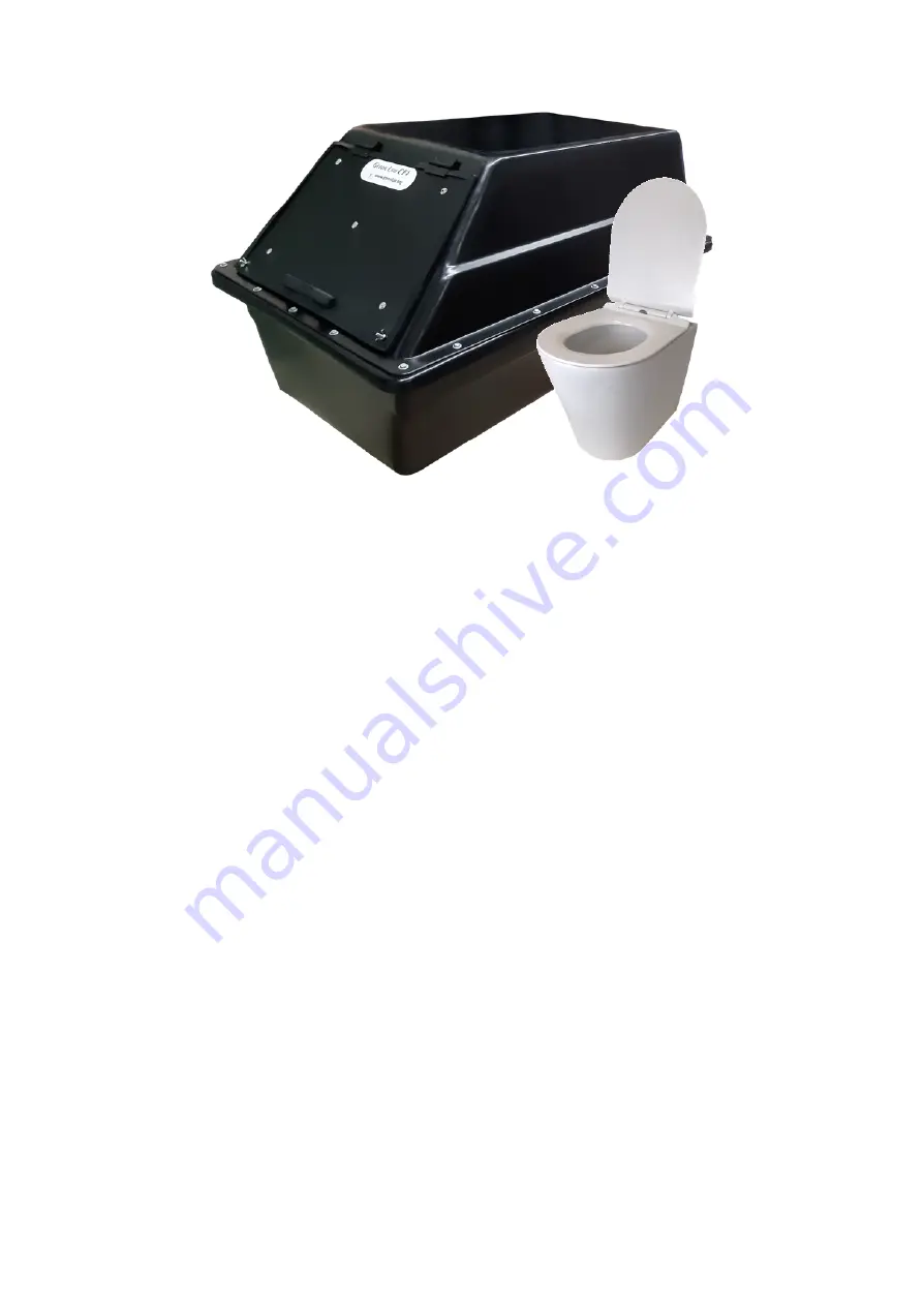
The CF 4 is supplied as a kit containing most of the components required and can be installed using basic
building tools and materials available at plumbing suppliers or hardware shops.

Installation of the CF 4 involves:

1. Assembly of the CF 4 composting container

2. Positioning the Pedestal and composting container to ensure a vertical drop from the pedestal to

the waste container

3. Preparing a flat, level, and firm base for the composting container to sit

4. Preparing the excess liquids dispersal trench

5. Connecting the Pedestal, waste chute and composting container

6. Installing the ventilation pipework, including fan and vent cowl

Summary of Contents for CF 4

Page 1: ...DRY COMPOSTING TOILET Owners Installation Operation Manual for the CF 4...

Page 2: ...ectrical supply 240VAC or 12VDC to the fan location unless the whirlybird option is selected The CF 4 is supplied as a kit containing most of the components required and can be installed using basic b...

Page 3: ...ss Do not plan to install a light directly over the pedestal waste chute as this will attract flying insects Always close the lid of the toilet after use Do not use your bathroom fan Its suction works...

Page 4: ...waste chute hole in the floor until you are sure you have everything lined up in case you need to adjust the position Prepare a flat level ground for the CF 4 and dig out the excess liquids trench Th...

Page 5: ...s final position 3 Do not yet connect up with slotted aggregate pipe of the excess liquids trench 4 Insert the drainage tray spacer pipes at the bottom and drain outlet service hole at the front 5 Sli...

Page 6: ...utting the chute to length Cut the waste chute hole in the toilet room floor to suit chute approx 250mm 2mm Insert the chute from above tapered end up through the hole you cut earlier Firmly rest the...

Page 7: ...4 and draw a 260mm circle and cut out with a jigsaw or similar Cut the Dektite along the marked line to suit the 250mm chute and fit the Dektite centrally over the chute hole screwing it down with the...

Page 8: ...oid bends tighter than 45 degrees in order to maximise air flow minimise the length of the piping between the composting container and the vent stack Warm air holding moisture entering a cold vent can...

Page 9: ...ver any items containing plastic e g including sanitary products should be placed into a separate bin A handful of covering material hemp 1 cup should be added after each bowel movement The composting...

Page 10: ...move the compost from the front of the unit as per steps 1 2 3 below a When the unit is full b after 6 months or c when fully broken down f Every 6 months check the excess liquids outlet via the servi...

Page 11: ...questions suggestions we are here to help Feedback is always welcome and is an invaluable part of providing an excellent product and service Finally thank you for being an integral part of the environ...

Reviews: